

Answered step by step
Verified Expert Solution
Question
1 Approved Answer
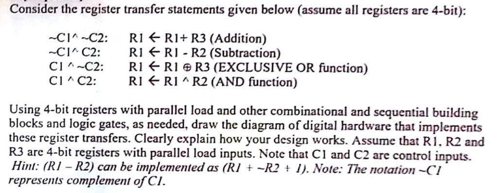
Consider the register transfer statements given below (assume all registers are 4-bit): CIA C2: RI *-RI+ R3 (Addition) -CI C2: RI f RI - R2
Step by Step Solution
There are 3 Steps involved in it
Step: 1

Get Instant Access to Expert-Tailored Solutions
See step-by-step solutions with expert insights and AI powered tools for academic success
Step: 2

Step: 3
Ace Your Homework with AI
Get the answers you need in no time with our AI-driven, step-by-step assistance
Get Started
Computer Aided Database Design
Authors: Antonio Albano, Valeria De Antonellis, A. Di Leva
1st Edition
0444877355, 978-0444877352