Question
Consider the simple potentiometer circuit shown in Figure 6.9 with reference to Figure 6.8. Perform a design-stage uncertainty analysis to determine the minimum uncertainty

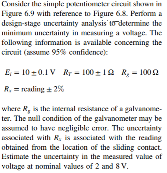
Consider the simple potentiometer circuit shown in Figure 6.9 with reference to Figure 6.8. Perform a design-stage uncertainty analysis to determine the minimum uncertainty in measuring a voltage. The following information is available concerning the circuit (assume 95% confidence): E = 10+ 0.1 V R = 10019 R = 10092 Rg Rx = reading 2% + where Rg is the internal resistance of a galvanome- ter. The null condition of the galvanometer may be assumed to have negligible error. The uncertainty associated with R is associated with the reading obtained from the location of the sliding contact. Estimate the uncertainty in the measured value of voltage at nominal values of 2 and 8 V.
Step by Step Solution
3.44 Rating (160 Votes )
There are 3 Steps involved in it
Step: 1

Get Instant Access to Expert-Tailored Solutions
See step-by-step solutions with expert insights and AI powered tools for academic success
Step: 2

Step: 3

Ace Your Homework with AI
Get the answers you need in no time with our AI-driven, step-by-step assistance
Get StartedRecommended Textbook for
Physics for Scientists and Engineers A Strategic Approach with Modern Physics
Authors: Randall D. Knight
4th edition
978-0134092508, 134092503, 133942651, 978-0133942651
Students also viewed these Electrical Engineering questions
Question
Answered: 1 week ago
Question
Answered: 1 week ago
Question
Answered: 1 week ago
Question
Answered: 1 week ago
Question
Answered: 1 week ago
Question
Answered: 1 week ago
Question
Answered: 1 week ago
Question
Answered: 1 week ago
Question
Answered: 1 week ago
Question
Answered: 1 week ago
Question
Answered: 1 week ago
Question
Answered: 1 week ago
Question
Answered: 1 week ago
Question
Answered: 1 week ago
Question
Answered: 1 week ago
Question
Answered: 1 week ago
Question
Answered: 1 week ago
Question
Answered: 1 week ago
Question
Answered: 1 week ago
Question
Answered: 1 week ago
Question
Answered: 1 week ago
Question
Answered: 1 week ago
View Answer in SolutionInn App


