Question
Create a Register File in VHDL that contains the register module, multiplexer, and decoder that you have previously written in vhdl. The register file contains
Create a Register File in VHDL that contains the register module, multiplexer, and decoder that you have previously written in vhdl.
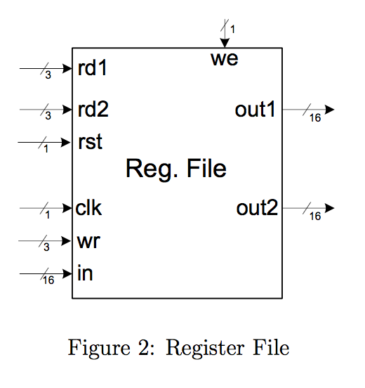
The register file contains eight register modules and follows a two-read, one-write format. See Figure 2 below.
Inputs (One bit unless noted otherwise):
rd1, rd2 (3 bits): Read1 and read2. Selects which registers to read from.
wr (3 bits): Write. Selects which register to write to. Note that the previous signals are 3 bits long, allow them to address all eight registers.
in (16 bits): Data to be written to the appropriate register.
clk: Clock signal.
we: Write enable. Enabling allows register contents to be written.
rst: Resets all registers. Asynchronous. Can be active high or low.
Outputs:
out1, out2 (16 bits): Parallel outputs containing the data from the selected registers.
Hints
-Use the output of the 3-to-8 decoder in conjunction with the register files we signal to in drive the we on the register
-Use two 8-to-1 MUXs, one to connect thenoutput of the register specified by rd1 to out1, and a second for rd2 and out2.
-Do not use parameters in the entity of the register file, however, generics should still be used when instantiating the various components. (Note: The reason for this is that the generic would then have to be set in a higher level, of which there are none.)

Step by Step Solution
There are 3 Steps involved in it
Step: 1

Get Instant Access to Expert-Tailored Solutions
See step-by-step solutions with expert insights and AI powered tools for academic success
Step: 2

Step: 3

Ace Your Homework with AI
Get the answers you need in no time with our AI-driven, step-by-step assistance
Get Started


