

Question: Create Entity Relational Diagram* Instructions An Entity Relationship diagram is one of the most important diagrams for any major piece of software. In fact, given
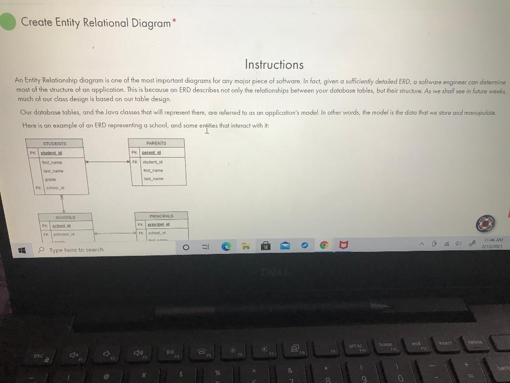


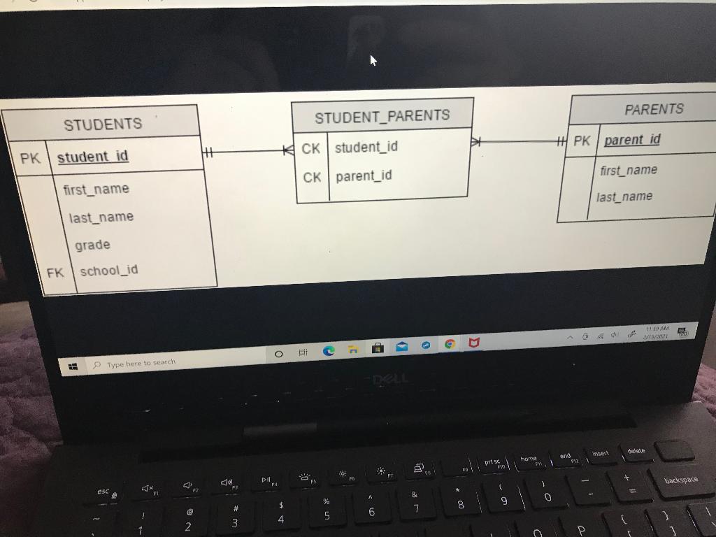
Create Entity Relational Diagram* Instructions An Entity Relationship diagram is one of the most important diagrams for any major piece of software. In fact, given a sufficiently detailed ERD, a software engineer can determine most of the structure of an application. This is because an ERD describes not only the relationships between your database tables, but their structure. As we shall see in future weeks, much of our class design is based on our table design. Our database tables, and the Java classes that will represent them, are referred to as an application's model. In other words, the model is the data that we store and manupulate. Here is an example of an ERD representing a school, and some entities that interact with it: PARENTS STUDENTS PK student id Sast name PK parented FK studentud last name first_name vrede last name FK 1 School SCHOOLS PRINCIPALS FKEncent id School FX orald FK school_id c O . O a TT.06 AM 2/9/27 C Type here to search del forts DIO ESC 1x 5 F A 8 * bart SO $ 8 name first_name address last name county tenure First, note that each table represents a single type of entity. We don't try to track students inside our school table, nor are we storing student information in the parent table. Secondly, notice that each table has a Primary Key, which also acts as a Foreign Key in another table. These form the basis of our relationships. Let's look at these relationships storting with Principals, and working clock-wise. Principals and Schools have a One-to-One relationship - every school has one principal, and every principal oversees only one school. This is shown by the '' mark on either side of the line. While we won't go over mandatory/optional relationships, note that this is a mandatory relationship (represented by an additional) on either side). A school must have a principal, and a principal must oversee a school for else he wouldn't be a principal). Each of these tables then has a reference to another entity. Schools and Students on the other hand, have a One-to-Many relationship. A single school has many students, but every student only belongs to one school. Additionally, only one side is mandatory ') the other side is optional ('O'). That is, a school does not need any students to still be a school but a student must attend a school to be a student. Students and Parents on the other hand, have a Many-to-Many relationship. A single student might have multiple parents, and a parent might have multiple students. This relationship is also mandatory - a student must have at least one parent, and a parent must have at least one student. Many to Many relationships are not common though, as they can be better handled by introducing an association table. Why is this Consider a spreadsheet representing the data in these two tables. Each row has a primary kery, which must be unique. To maintain the relationship, coach row must also have a foreign key column that represents the other table. A student must have a link to a parent, and a parent must have a link to its child. This work well so long as we have one childhood one poront. But if you introduce a second child, you will need to have a second row in the paranluble to store that second farmyn key, and this duplicates all of the parental information in the first row, and violates our primary key constraint Similarly, if you try to track a second parent, each student must have two rows in the Student table, and this causes similar problems So instead of suffering a poorly designed database, we create an association table. The minimum columns an association table must have are loreign key references to the two other tables, and each unique combination of the two foreign keys representa composite key. Lach of the two trbles in question the maintaines One-ra Mony relationship with the association table. This is pictured below: 7147 AM w Type here to search home pots YE end 912 FE 94 DI ASC + 1 backspars & % 0 9 1 8 4 7 5 6 2 3 0 1 Y T U W R E Dombourg LOUISES WISS REVATURE US CKS OXO Your task is to create an Entity Relationship Diagram that represents the database required for PubHub. Remember that tags are just descriptive bits of text like "fiction" or "female protagonist." You do not need to track any additional information for tags. The BOOK TAGS table should have the following columns Isbn_13 log.name BOOK_TAGS isbn 13 will be a foreign key to BOOKS isbn 13. Together, BOOK TAGS. isbn_13 and BOOK_TAGSlag_name will operate as a composite key. The table BOOKS should have a one-to-many relationship with BOOK_TAGS, You can create. His diagram in any program you wish, but we recommend using the Draw.o app, which is linked in the Reference Section. When you create a diagcorn with dewi you can export it as an image file by going to "File" > "Export cs' and selecting either PNG or JPEG file When you are done, upload the file below Upload Artifacts Allowed fle types: zip, rar, doc, docx, ipg, png, jpeg, gif, bmp, till farge pdf file name Completed Entity Relational Diagram Maximum File size. 20 MB YAM M Type here to search Delvete ese > 47 * % $ & # 1 0 backagane 1 3 4 8 2 5 6 7 } P Y Q W tab E R T PARENTS STUDENTS STUDENT_PARENTS PK parent id HT *CK student_id PK student id first_name CK parent_id first_name last_name last_name grade FK school_id 15 AM 27/01 C Type here to search est dete and 542 home 04 prisc do FY FA backspace ) CTX esc A B 0 % 9 # $ 8 @ 7 6 1 4 5 1 2 3 Create Entity Relational Diagram* Instructions An Entity Relationship diagram is one of the most important diagrams for any major piece of software. In fact, given a sufficiently detailed ERD, a software engineer can determine most of the structure of an application. This is because an ERD describes not only the relationships between your database tables, but their structure. As we shall see in future weeks, much of our class design is based on our table design. Our database tables, and the Java classes that will represent them, are referred to as an application's model. In other words, the model is the data that we store and manupulate. Here is an example of an ERD representing a school, and some entities that interact with it: PARENTS STUDENTS PK student id Sast name PK parented FK studentud last name first_name vrede last name FK 1 School SCHOOLS PRINCIPALS FKEncent id School FX orald FK school_id c O . O a TT.06 AM 2/9/27 C Type here to search del forts DIO ESC 1x 5 F A 8 * bart SO $ 8 name first_name address last name county tenure First, note that each table represents a single type of entity. We don't try to track students inside our school table, nor are we storing student information in the parent table. Secondly, notice that each table has a Primary Key, which also acts as a Foreign Key in another table. These form the basis of our relationships. Let's look at these relationships storting with Principals, and working clock-wise. Principals and Schools have a One-to-One relationship - every school has one principal, and every principal oversees only one school. This is shown by the '' mark on either side of the line. While we won't go over mandatory/optional relationships, note that this is a mandatory relationship (represented by an additional) on either side). A school must have a principal, and a principal must oversee a school for else he wouldn't be a principal). Each of these tables then has a reference to another entity. Schools and Students on the other hand, have a One-to-Many relationship. A single school has many students, but every student only belongs to one school. Additionally, only one side is mandatory ') the other side is optional ('O'). That is, a school does not need any students to still be a school but a student must attend a school to be a student. Students and Parents on the other hand, have a Many-to-Many relationship. A single student might have multiple parents, and a parent might have multiple students. This relationship is also mandatory - a student must have at least one parent, and a parent must have at least one student. Many to Many relationships are not common though, as they can be better handled by introducing an association table. Why is this Consider a spreadsheet representing the data in these two tables. Each row has a primary kery, which must be unique. To maintain the relationship, coach row must also have a foreign key column that represents the other table. A student must have a link to a parent, and a parent must have a link to its child. This work well so long as we have one childhood one poront. But if you introduce a second child, you will need to have a second row in the paranluble to store that second farmyn key, and this duplicates all of the parental information in the first row, and violates our primary key constraint Similarly, if you try to track a second parent, each student must have two rows in the Student table, and this causes similar problems So instead of suffering a poorly designed database, we create an association table. The minimum columns an association table must have are loreign key references to the two other tables, and each unique combination of the two foreign keys representa composite key. Lach of the two trbles in question the maintaines One-ra Mony relationship with the association table. This is pictured below: 7147 AM w Type here to search home pots YE end 912 FE 94 DI ASC + 1 backspars & % 0 9 1 8 4 7 5 6 2 3 0 1 Y T U W R E Dombourg LOUISES WISS REVATURE US CKS OXO Your task is to create an Entity Relationship Diagram that represents the database required for PubHub. Remember that tags are just descriptive bits of text like "fiction" or "female protagonist." You do not need to track any additional information for tags. The BOOK TAGS table should have the following columns Isbn_13 log.name BOOK_TAGS isbn 13 will be a foreign key to BOOKS isbn 13. Together, BOOK TAGS. isbn_13 and BOOK_TAGSlag_name will operate as a composite key. The table BOOKS should have a one-to-many relationship with BOOK_TAGS, You can create. His diagram in any program you wish, but we recommend using the Draw.o app, which is linked in the Reference Section. When you create a diagcorn with dewi you can export it as an image file by going to "File" > "Export cs' and selecting either PNG or JPEG file When you are done, upload the file below Upload Artifacts Allowed fle types: zip, rar, doc, docx, ipg, png, jpeg, gif, bmp, till farge pdf file name Completed Entity Relational Diagram Maximum File size. 20 MB YAM M Type here to search Delvete ese > 47 * % $ & # 1 0 backagane 1 3 4 8 2 5 6 7 } P Y Q W tab E R T PARENTS STUDENTS STUDENT_PARENTS PK parent id HT *CK student_id PK student id first_name CK parent_id first_name last_name last_name grade FK school_id 15 AM 27/01 C Type here to search est dete and 542 home 04 prisc do FY FA backspace ) CTX esc A B 0 % 9 # $ 8 @ 7 6 1 4 5 1 2 3
Step by Step Solution
There are 3 Steps involved in it

Get step-by-step solutions from verified subject matter experts