Answered step by step
Verified Expert Solution
Question
1 Approved Answer
Lab Description: A PLC will control an automatic packaging machine. A conveyor transports the bottles to a bundler machine to form a 6 pack,


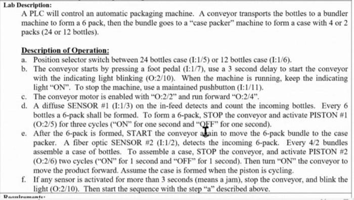
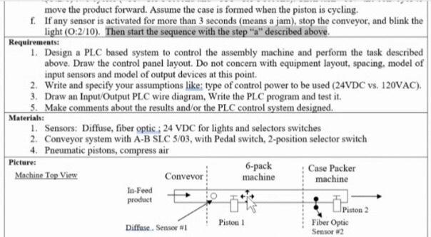
Lab Description: A PLC will control an automatic packaging machine. A conveyor transports the bottles to a bundler machine to form a 6 pack, then the bundle goes to a "case packer" machine to form a case with 4 or 2 packs (24 or 12 bottles). Description of Operation: a. Position selector switch between 24 bottles case (1:1/5) or 12 bottles case (1:1/6). b. The conveyor starts by pressing a foot pedal (1:1/7), use a 3 second delay to start the conveyor with the indicating light blinking (0:2/10). When the machine is running, keep the indicating light "ON". To stop the machine, use a maintained pushbutton (1:1/11). c. The conveyor motor is enabled with "O:2/2" and run forward "O:2/4". d. A diffuse SENSOR #1 (I:1/3) on the in-feed detects and count the incoming bottles. Every 6 bottles a 6-pack shall be formed. To form a 6-pack, STOP the conveyor and activate PISTON #1 (0:2/5) for three cycles ("ON" for one second and "QFF" for one second). e. After the 6-pack is formed, START the conveyor akain to move the 6-pack bundle to the case packer. A fiber optic SENSOR #2 (1:1/2), detects the incoming 6-pack. Every 4/2 bundles assemble a case of bottles. To assemble a case, STOP the conveyor, and activate PISTON #2 (0:2/6) two cycles ("ON" for 1 second and "OFF" for 1 second). Then turn "ON" the conveyor to move the product forward. Assume the case is formed when the piston is cycling. f. If any sensor is activated for more than 3 seconds (means a jam), stop the conveyor, and blink the light (0:2/10). Then start the sequence with the step "a" described above. Danniromante. move the product forward. Assume the case is formed when the piston is cycling. f. If any sensor is activated for more than 3 seconds (means a jam), stop the conveyor, and blink the light (0:2/10). Then start the sequence with the step "a" described above. Requirements: 1. Design a PLC based system to control the assembly machine and perform the task described above. Draw the control panel layout. Do not concern with equipment layout, spacing, model of input sensors and model of output devices at this point. 2. Write and specify your assumptions like: type of control power to be used (24VDC vs. 120VAC). 3. Draw an Input/Output PLC wire diagram, Write the PLC program and test it. 5. Make comments about the results and/or the PLC control system designed. Materials: 1. Sensors: Diffuse, fiber optic; 24 VDC for lights and selectors switches 2. Conveyor system with A-B SLC 5/03, with Pedal switch, 2-position selector switch 4. Pneumatic pistons, compress air Picture: Machine Top View In-Feed product Convevor Diffuse. Sensor #1 6-pack machine Piston 1 Case Packer machine Piston 2 Fiber Optic Sensor #2
Step by Step Solution
★★★★★
3.54 Rating (154 Votes )
There are 3 Steps involved in it
Step: 1
Here I000 is START PBNO B300 VIRTUAL OUTPUT T40 TIMER 0 ONDELAY T41 TIMER 1 O...
Get Instant Access to Expert-Tailored Solutions
See step-by-step solutions with expert insights and AI powered tools for academic success
Step: 2

Step: 3

Ace Your Homework with AI
Get the answers you need in no time with our AI-driven, step-by-step assistance
Get Started


