Answered step by step
Verified Expert Solution
Question
1 Approved Answer
Cylinder B Cylinder A Cylinder Fig Q1 (a) Fig Q1 (a) illustratcs a machine designed to drill two cqual sized holes close together in rectangular
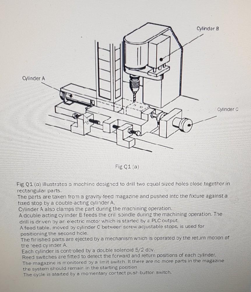
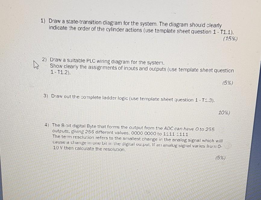
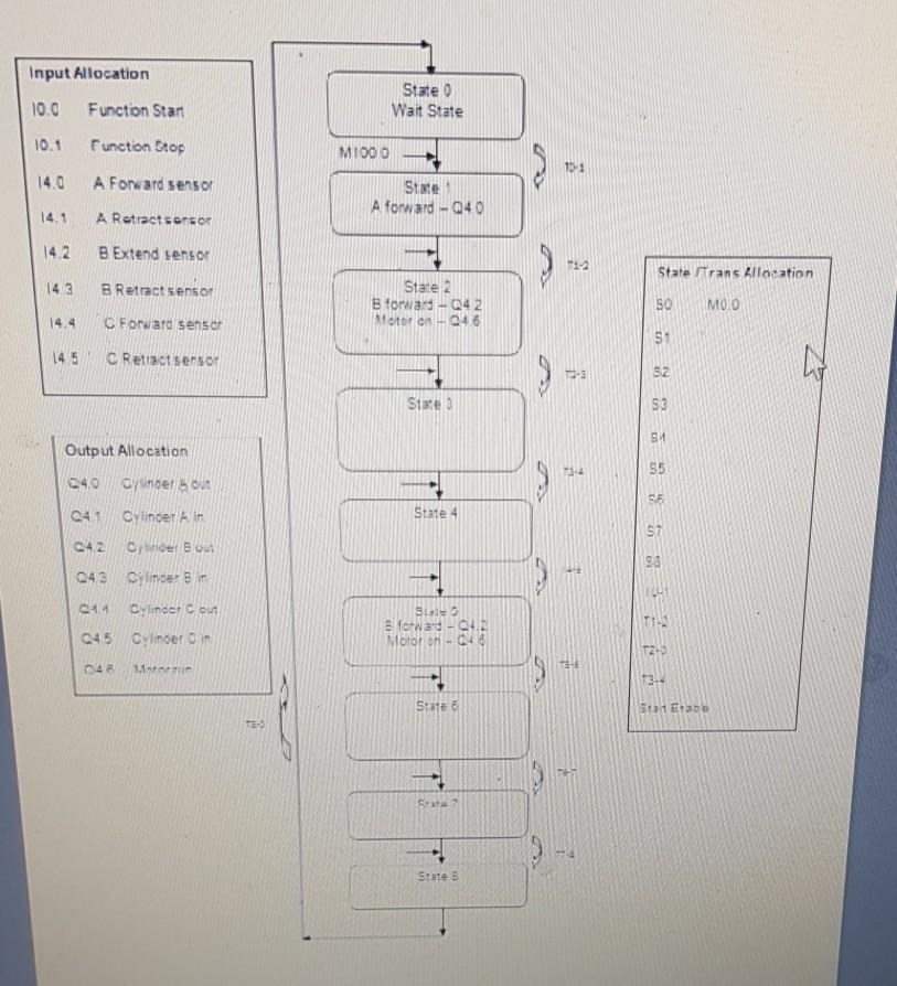
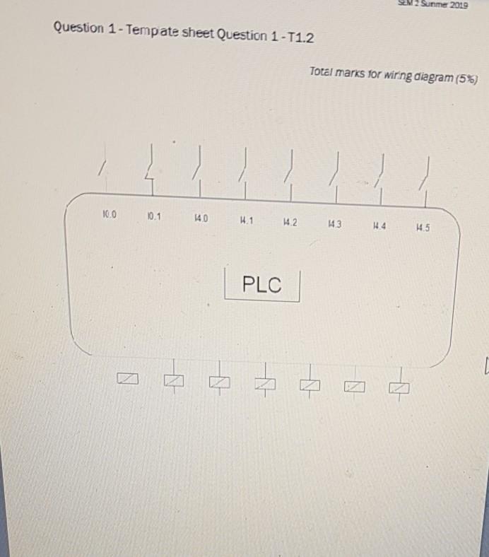




Cylinder B Cylinder A Cylinder Fig Q1 (a) Fig Q1 (a) illustratcs a machine designed to drill two cqual sized holes close together in rectangular paits. The parts are taken from a gravity-feed magazine and pushed into the fixture against a fixed stop by a couble-acting cylinder A. Cylinder A also clamps the part during the machining operation. A double acting cylinder E feeds the dril spindle during the machining operation. The drill is driven by an electric motor which is started by a PLC output A feed table, moved by cylinder C between screw adjustable stops, is used for positioning the second hcle, The finished parts are ejected by a mechanism which is operated by the return motion of tre reed cy inder A. Each cylinder is controlled by a double solenoid 5/2 dov. Reed switches are fitted to detect the forward and return positions of each cylinder. The magazine is monitored by a limit switch. It there are no more parts in the magazine the system should remair in the starting position The cycle is started by a momentary contact push-button switch. 1) Draw a state-transition diagram for the system. The diagram should clearly indicate the order of the cylinder actions (use template sheet question 1. T1.1). (15%) 2) Draw a suitable PLC wiring diagram for the system. Show clearly the assignments of inputs and outputs (use template sheet question 1-T1.2). (5%) 3) Draw out the complete ladder logic (use template sheet question 1-T1.3). 10%) 4) The 8-bit digital Byte that forms the output from the ADC can have 0 to 255 outputs, giving 256 different values. 0000 0000 to 1111 1111 The term resolution refers to the smallest change in the analog signal which will Cause a change in one bil in the digital ou pul. If an analog signal varies from O- 10 V then calculate the resolution. (5%) Input Allocation 10.0 State 0 Wait State Function Start 10.1 Function Stop MI000 153 14.0 A Forward sensor State A forward - 240 A Retract sensor B Extend sensor State Trans Allocation 143 B Retract sensor State 2 B forward-042 Motor on 046 SO MOO 14.4 C Forward sensor si 145 C Retract sensor SZ Stare S3 91 Output Allocation 55 C40 owner out 041 Oylinder A in State 4 ST Q42 Or hoer Boer 043 Cylinder in ++ 98 19 Cylinder Cou! Sias Blow - 4 Motor on-048 045 Cymoer in T2-3 13.4 State 1 EM TH SH States summe 2019 Question 1 - Tempate sheet Question 1-T1.2 Total marks for wiring diagram (5%) 100 101 40 41 42 143 114 15 PLC N bod Initial Conditions Cycle Start, Cyde Stop, StartEnable) Transitions States Qutputs Timers Cylinder B Cylinder A Cylinder Fig Q1 (a) Fig Q1 (a) illustratcs a machine designed to drill two cqual sized holes close together in rectangular paits. The parts are taken from a gravity-feed magazine and pushed into the fixture against a fixed stop by a couble-acting cylinder A. Cylinder A also clamps the part during the machining operation. A double acting cylinder E feeds the dril spindle during the machining operation. The drill is driven by an electric motor which is started by a PLC output A feed table, moved by cylinder C between screw adjustable stops, is used for positioning the second hcle, The finished parts are ejected by a mechanism which is operated by the return motion of tre reed cy inder A. Each cylinder is controlled by a double solenoid 5/2 dov. Reed switches are fitted to detect the forward and return positions of each cylinder. The magazine is monitored by a limit switch. It there are no more parts in the magazine the system should remair in the starting position The cycle is started by a momentary contact push-button switch. 1) Draw a state-transition diagram for the system. The diagram should clearly indicate the order of the cylinder actions (use template sheet question 1. T1.1). (15%) 2) Draw a suitable PLC wiring diagram for the system. Show clearly the assignments of inputs and outputs (use template sheet question 1-T1.2). (5%) 3) Draw out the complete ladder logic (use template sheet question 1-T1.3). 10%) 4) The 8-bit digital Byte that forms the output from the ADC can have 0 to 255 outputs, giving 256 different values. 0000 0000 to 1111 1111 The term resolution refers to the smallest change in the analog signal which will Cause a change in one bil in the digital ou pul. If an analog signal varies from O- 10 V then calculate the resolution. (5%) Input Allocation 10.0 State 0 Wait State Function Start 10.1 Function Stop MI000 153 14.0 A Forward sensor State A forward - 240 A Retract sensor B Extend sensor State Trans Allocation 143 B Retract sensor State 2 B forward-042 Motor on 046 SO MOO 14.4 C Forward sensor si 145 C Retract sensor SZ Stare S3 91 Output Allocation 55 C40 owner out 041 Oylinder A in State 4 ST Q42 Or hoer Boer 043 Cylinder in ++ 98 19 Cylinder Cou! Sias Blow - 4 Motor on-048 045 Cymoer in T2-3 13.4 State 1 EM TH SH States summe 2019 Question 1 - Tempate sheet Question 1-T1.2 Total marks for wiring diagram (5%) 100 101 40 41 42 143 114 15 PLC N bod Initial Conditions Cycle Start, Cyde Stop, StartEnable) Transitions States Qutputs Timers
Step by Step Solution
There are 3 Steps involved in it
Step: 1

Get Instant Access to Expert-Tailored Solutions
See step-by-step solutions with expert insights and AI powered tools for academic success
Step: 2

Step: 3

Ace Your Homework with AI
Get the answers you need in no time with our AI-driven, step-by-step assistance
Get Started


