Answered step by step
Verified Expert Solution
Question
1 Approved Answer
D= 0 4. For the following circuit diagram, Use the Boolean algebra notation: A, (for not A); AB (for A and B), A + B
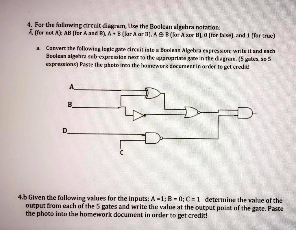
D= 0
4. For the following circuit diagram, Use the Boolean algebra notation: A, (for not A); AB (for A and B), A + B (for A or B), AB (for A xor B), 0 (for false), and 1 (for true) Convert the following logic gate circuit into a Boolean Algebra expression; write it and each Boolean algebra sub-expression next to the appropriate gate in the diagram. (5 gates, so 5 expressions) Paste the photo into the homework document in order to get credit! a. D. 4b Given the following values for the inputs A=1;B=0;C=1 determine the value ofthe output from each of the 5 gates and write the value at the output point of the gate. Paste the photo into the homework document in order to get creditStep by Step Solution
There are 3 Steps involved in it
Step: 1
Get Instant Access to Expert-Tailored Solutions
See step-by-step solutions with expert insights and AI powered tools for academic success
Step: 2
Step: 3
Ace Your Homework with AI
Get the answers you need in no time with our AI-driven, step-by-step assistance
Get Started