Answered step by step
Verified Expert Solution
Question
1 Approved Answer
d d d Materials (Steel HR) Material of the shaft Material of the lower link Material of the pin B Material of the brackets

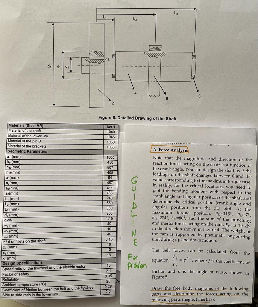
d d d Materials (Steel HR) Material of the shaft Material of the lower link Material of the pin B Material of the brackets Geometric Parameters 12 L3 Figure 6. Detailed Drawing of the Shaft Set 1 1040 1045 1050 1035 1000 450 507 408 54 CHIALINE problem A. Force Analysis Note that the magnitude and direction of the reaction forces acting on the shaft is a function of the crank angle. You can design the shaft as if the loadings on the shaft changes between 0 and the value corresponding to the maximum torque case. In reality, for the critical locations, you need to plot the bending moment with respect to the crank angle and angular position of the shaft and determine the critical position (crank angle and angular position) from the 3D plot. At the maximum torque position, 812-115, 013-7, 014-274, 015-86, and the sum of the punching and inertia forces acting on the ram, Fp, is 10 kN in the direction shown in Figure 4. The weight of the ram is supported by pneumatic supporting unit during up and down motion. The belt forces can be calculated from the equation, Fea, where f is the coefficient of F friction and a is the angle of wrap, shown in Figure 5. Draw the free body diagrams of the following parts and determine the forces acting on the following parts (neglect inertias). a(mm) h(mm) a12(mm) h12(mm) az(mm) as(mm) a(mm) as(mm) L (mm) 457 411 435 240 L2 (mm) L3 (mm) d3 (mm) d/d W (mm) 550 860 800 1.15 40 10 W (mm) 40 Wa (mm) r/d of fillets on the shaft 0.15 10 Xa (mm) 10 X (mm) 18 Xc (mm) Far Design Specifications Speed ratio of the flywheel and the electric motor 16 2.1 Factor of safety 0.95 Reliability 25 Ambient temperature (C) Br Coefficient of friction between the belt and the flywheel Side to side ratio in the lower link 0.28 2.0
Step by Step Solution
There are 3 Steps involved in it
Step: 1

Get Instant Access to Expert-Tailored Solutions
See step-by-step solutions with expert insights and AI powered tools for academic success
Step: 2

Step: 3

Ace Your Homework with AI
Get the answers you need in no time with our AI-driven, step-by-step assistance
Get Started


