

Question
Describe the effect that a single stuck-at-0 fault would have for the signals shown below, in the single-cycle datapath in Figure 5.17. Which instructions, if
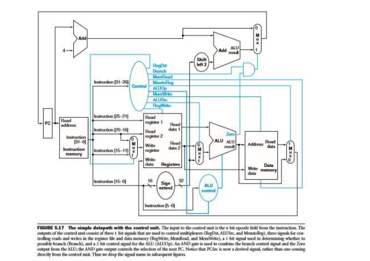
Describe the effect that a single stuck-at-0 fault would have for the signals shown below, in the single-cycle datapath in Figure 5.17. Which instructions, if any, will not work correctly? Explain why. Consider each of the following faults separately: a. RegWrite = 0 b. ALUop1 = 0 c. ALUop0=0 c. Branch = 0 d. MemRead = 0 e. MemWrite = 0
ALU Shift left 2 ALUSic 521 Road Road rogisder f Read data t rogeder 2 20-16 31-0 ogindor data 2 data 16 Sigm extend 15-0 32 ALU control Instruction 15- FIGURE 5.17 The simple datapath with the control unit. The inpat to the control unit is the 6 bit opcode field from the instraction. The outputs of the control unit comist of three I bit signals that are used to control nltiplesors (RegDst, ALISec, and MemioRay), three signals for con trolling reals and writes in the egister file and data me nory (Regwrite Menkeal, anl MeWrite), a bit signal ised in determin ng whether to possibly branch (Branch), and a 2-bit control signal for the ALLU (ALLOp). An AND gate is used to combine the branch control signal and the Zeso outpuhom the ALU: the AND gle output controls the selection of the next K. Notice that KMc is now a lerived segnal father than one coming directly from the control unit.Thas we drop the signal name in beqent figuresStep by Step Solution
There are 3 Steps involved in it
Step: 1

Get Instant Access to Expert-Tailored Solutions
See step-by-step solutions with expert insights and AI powered tools for academic success
Step: 2

Step: 3
Ace Your Homework with AI
Get the answers you need in no time with our AI-driven, step-by-step assistance
Get Started
Lnai 12458 Machine Learning And Knowledge Discovery In Databases European Conference Ecml Pkdd 2020 Ghent Belgium September 14 18 2020 Proceedings Part 2 Lnai 12458
Authors: Frank Hutter ,Kristian Kersting ,Jefrey Lijffijt ,Isabel Valera
1st Edition
3030676609, 978-3030676605