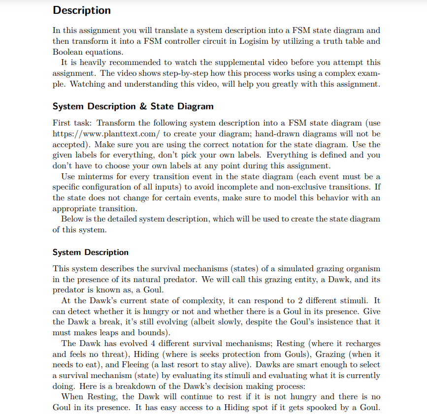
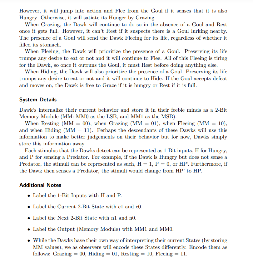
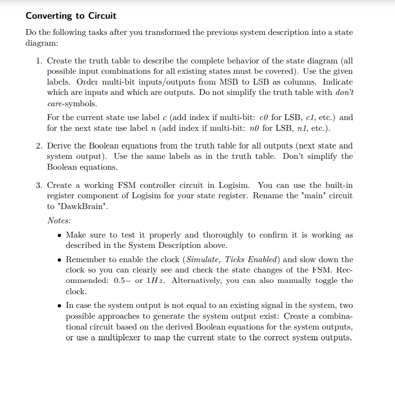
Description In this assignment you will translate a system description into a FSM state diagram and then transform it into a FSM controller circuit in Logisim by utilizing a truth table and Boolean equations. It is heavily recommended to watch the supplemental video before you attempt this assignment. The video shows step-by-step how this process works using a complex exam- ple. Watching and understanding this video, will help you greatly with this assignment. System Description & State Diagram First task: Transform the following system description into a FSM state diagram (use https://www.planttext.com/ to create your diagram; hand-drawn diagrams will not be accepted). Make sure you are using the correct notation for the state diagram. Use the given labels for everything, don't pick your own labels. Everything is defined and you don't have to choose your own labels at any point during this assignment. Use minterms for every transition event in the state diagram (each event must be a specific configuration of all inputs) to avoid incomplete and non-exclusive transitions. If the state does not change for certain events, make sure to model this behavior with an appropriate transition. Below is the detailed system description, which will be used to create the state diagram of this system. System Description This system describes the survival mechanisms (states) of a simulated grazing organism in the presence of its natural predator. We will call this grazing entity, a Dawk, and its predator is known as, a Goul. At the Dawk's current state of complexity, it can respond to 2 different stimuli. It can detect whether it is hungry or not and whether there is a Goul in its presence. Give the Dawk a break, it's still evolving (albeit slowly, despite the Goul's insistence that it must makes leaps and bounds). The Dawk has evolved 4 different survival mechanisms; Resting (where it recharges and feels no threat), Hiding (where is seeks protection from Gouls), Grazing (when it needs to eat), and Fleeing (a last resort to stay alive). Dawks are smart enough to select a survival mechanism (state) by evaluating its stimuli and evaluating what it is currently doing. Here is a breakdown of the Dawk's decision making process: When Resting, the Dawk will continue to rest if it is not hungry and there is no Goul in its presence. It has easy access to a Hiding spot if it gets spooked by a Goul. However, it will jump into action and Flee from the Goul if it senses that it is also Hungry. Otherwise, it will satiate its Hunger by Grazing. When Grazing, the Dawk will continue to do so in the absence of a Goul and Rest once it gets full. However, it can't Rest if it suspects there is a Goul lurking nearby. The presence of a Goul will send the Dawk Fleeing for its life, regardless of whether it filled its stomach. When Fleeing, the Dawk will prioritize the presence of a Goul. Preserving its life trumps any desire to eat or not and it will continue to Flee. All of this Fleeing is tiring for the Dawk, so once it outruns the Goul, it must Rest before doing anything else. When Hiding, the Dawk will also prioritize the presence of a Goul. Preserving its life trumps any desire to eat or not and it will continue to Hide. If the Goul accepts defeat and moves on, the Dawk is free to Graze if it is hungry or Rest if it is full. System Details Dawk's internalize their current behavior and store it in their feeble minds as a 2-Bit Memory Module (MM: MMO as the LSB, and MM1 as the MSB). When Resting (MM = 00), when Grazing (MM = 01), when Fleeing (MM = 10), and when Hiding (MM = 11). Perhaps the descendants of these Dawks will use this information to make better judgements on their behavior but for now, Dawks simply store this information away. Each stimulus that the Dawks detect can be represented as 1-Bit inputs, H for Hungry, and P for sensing a Predator. For example, if the Dawk is Hungry but does not sense a Predator, the stimuli can be represented as such, H = 1, P = 0, or HP? Furthermore, if the Dawk then senses a Predator, the stimuli would change from HP to HP. Additional Notes Label the 1-Bit Inputs with H and P. Label the Current 2-Bit State with cl and co. Label the Next 2-Bit State with nl and no. Label the Output (Memory Module) with MM1 and MMO. While the Dawks have their own way of interpreting their current States (by storing MM values), we as observers will encode these States differently. Encode them as follows: Grazing = 00, Hiding = 01, Resting = 10, Fleeing = 11. Converting to Circuit Do the following tasks after you transformed the previous system description into a state diagram: 1. Create the truth table to describe the complete behavior of the state diagram (all possible input combinations for all existing states must be covered). Use the given labels. Order multi-bit inputs/outputs from MB to LSB as columns. Indicate which are inputs and which are outputs. Do not simplify the truth table with don't care-symbols. For the current state use label c (add index if multi-bit: c0 for LSB, cl, etc.) and for the next state use label n (add index if multi-bit: n0 for LSB, n1, etc.). 2. Derive the Boolean equations from the truth table for all outputs (next state and system output). Use the same labels as in the truth table. Don't simplify the Boolean equations. 3. Create a working FSM controller circuit in Logisim. You can use the built-in register component of Logisim for your state register. Rename the "main" circuit to 'DawkBrain'. Notes: Make sure to test it properly and thoroughly to confirm it is working as described in the System Description above. Remember to enable the clock (Simulate, Ticks Enabled) and slow down the clock so you can clearly see and check the state changes of the FSM. Rec- ommended: 0.5, or 1Hz. Alternatively, you can also manually toggle the clock. In case the system output is not equal to an existing signal in the system, two possible approaches to generate the system output exist: Create a combina- tional circuit based on the derived Boolean equations for the system outputs, or use a multiplexer to map the current state to the correct system outputs. Description In this assignment you will translate a system description into a FSM state diagram and then transform it into a FSM controller circuit in Logisim by utilizing a truth table and Boolean equations. It is heavily recommended to watch the supplemental video before you attempt this assignment. The video shows step-by-step how this process works using a complex exam- ple. Watching and understanding this video, will help you greatly with this assignment. System Description & State Diagram First task: Transform the following system description into a FSM state diagram (use https://www.planttext.com/ to create your diagram; hand-drawn diagrams will not be accepted). Make sure you are using the correct notation for the state diagram. Use the given labels for everything, don't pick your own labels. Everything is defined and you don't have to choose your own labels at any point during this assignment. Use minterms for every transition event in the state diagram (each event must be a specific configuration of all inputs) to avoid incomplete and non-exclusive transitions. If the state does not change for certain events, make sure to model this behavior with an appropriate transition. Below is the detailed system description, which will be used to create the state diagram of this system. System Description This system describes the survival mechanisms (states) of a simulated grazing organism in the presence of its natural predator. We will call this grazing entity, a Dawk, and its predator is known as, a Goul. At the Dawk's current state of complexity, it can respond to 2 different stimuli. It can detect whether it is hungry or not and whether there is a Goul in its presence. Give the Dawk a break, it's still evolving (albeit slowly, despite the Goul's insistence that it must makes leaps and bounds). The Dawk has evolved 4 different survival mechanisms; Resting (where it recharges and feels no threat), Hiding (where is seeks protection from Gouls), Grazing (when it needs to eat), and Fleeing (a last resort to stay alive). Dawks are smart enough to select a survival mechanism (state) by evaluating its stimuli and evaluating what it is currently doing. Here is a breakdown of the Dawk's decision making process: When Resting, the Dawk will continue to rest if it is not hungry and there is no Goul in its presence. It has easy access to a Hiding spot if it gets spooked by a Goul. However, it will jump into action and Flee from the Goul if it senses that it is also Hungry. Otherwise, it will satiate its Hunger by Grazing. When Grazing, the Dawk will continue to do so in the absence of a Goul and Rest once it gets full. However, it can't Rest if it suspects there is a Goul lurking nearby. The presence of a Goul will send the Dawk Fleeing for its life, regardless of whether it filled its stomach. When Fleeing, the Dawk will prioritize the presence of a Goul. Preserving its life trumps any desire to eat or not and it will continue to Flee. All of this Fleeing is tiring for the Dawk, so once it outruns the Goul, it must Rest before doing anything else. When Hiding, the Dawk will also prioritize the presence of a Goul. Preserving its life trumps any desire to eat or not and it will continue to Hide. If the Goul accepts defeat and moves on, the Dawk is free to Graze if it is hungry or Rest if it is full. System Details Dawk's internalize their current behavior and store it in their feeble minds as a 2-Bit Memory Module (MM: MMO as the LSB, and MM1 as the MSB). When Resting (MM = 00), when Grazing (MM = 01), when Fleeing (MM = 10), and when Hiding (MM = 11). Perhaps the descendants of these Dawks will use this information to make better judgements on their behavior but for now, Dawks simply store this information away. Each stimulus that the Dawks detect can be represented as 1-Bit inputs, H for Hungry, and P for sensing a Predator. For example, if the Dawk is Hungry but does not sense a Predator, the stimuli can be represented as such, H = 1, P = 0, or HP? Furthermore, if the Dawk then senses a Predator, the stimuli would change from HP to HP. Additional Notes Label the 1-Bit Inputs with H and P. Label the Current 2-Bit State with cl and co. Label the Next 2-Bit State with nl and no. Label the Output (Memory Module) with MM1 and MMO. While the Dawks have their own way of interpreting their current States (by storing MM values), we as observers will encode these States differently. Encode them as follows: Grazing = 00, Hiding = 01, Resting = 10, Fleeing = 11. Converting to Circuit Do the following tasks after you transformed the previous system description into a state diagram: 1. Create the truth table to describe the complete behavior of the state diagram (all possible input combinations for all existing states must be covered). Use the given labels. Order multi-bit inputs/outputs from MB to LSB as columns. Indicate which are inputs and which are outputs. Do not simplify the truth table with don't care-symbols. For the current state use label c (add index if multi-bit: c0 for LSB, cl, etc.) and for the next state use label n (add index if multi-bit: n0 for LSB, n1, etc.). 2. Derive the Boolean equations from the truth table for all outputs (next state and system output). Use the same labels as in the truth table. Don't simplify the Boolean equations. 3. Create a working FSM controller circuit in Logisim. You can use the built-in register component of Logisim for your state register. Rename the "main" circuit to 'DawkBrain'. Notes: Make sure to test it properly and thoroughly to confirm it is working as described in the System Description above. Remember to enable the clock (Simulate, Ticks Enabled) and slow down the clock so you can clearly see and check the state changes of the FSM. Rec- ommended: 0.5, or 1Hz. Alternatively, you can also manually toggle the clock. In case the system output is not equal to an existing signal in the system, two possible approaches to generate the system output exist: Create a combina- tional circuit based on the derived Boolean equations for the system outputs, or use a multiplexer to map the current state to the correct system outputs