

Question
Design a 32 bit register. A 32 bit register needs to be designed in logism. Below are a few hints and a description of what
Design a 32 bit register.
A 32 bit register needs to be designed in logism. Below are a few hints and a description of what the inputs and the outputs of the register needs to do. A register file also lets the surrounding circuitry optionally write to one register, which is also chosen dynamically. In this lab, you will build a register file that has two read ports and one write port. That means that your register file circuit should let outside circuitry read two registers at a 1 time while also supporting writing to one register at a time. You should support eight registers total. Each register must hold 32 bits of data.
Input/output descriptions
ReadRegister1 specifies which register should be read from. That registers data should be presented on the ReadData1 output.
ReadRegister2 specifies which register should be read from. That registers data should be presented on the ReadData2 output.
WriteRegister specifies which register should be written to.
WriteData is the data that will be written to the register specified by WriteRegister. On a rising clock edge, the data will be written to the specified register.
WriteEnable, if true, will cause the WriteData to be written to the register specified by Write-Register; otherwise, WriteData will be ignored and no register will be written to.
Clock conveys the clock signal.
Hints
1. Since the registers are 32 bits wide, and since ReadData1 will output the entire contents of a register, ReadData1 will be 32 bits wide. By the same reasoning, ReadData2 will be 32 bits wide.
2. Since you need 8 registers, then 3 bits are needed to name each register. The register having the name 000 is register 0, 001 is register 1, 010 is register 2, and so on.
3. ReadRegister1 and ReadRegister2 are therefore each 3 bits wide.
4. WriteRegister describes which register of the eight registers is being written to. Therefore,
5. Writ-eRegister is 3 bits wide.
6. WriteData specifies the data that will be written into a register. Since the registers are 32 bits, WriteData will be 32 bits.
7. WriteEnable says whether or not a register write should actually be performed (yes or no). 8. Therefore, WriteEnable is 1 bit wide.
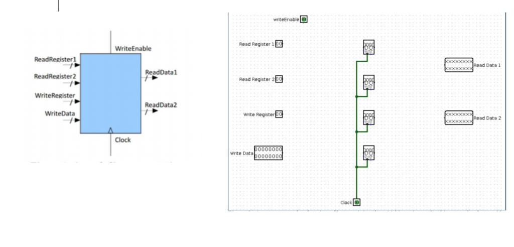
The picture below on the left is the symbolic representation of the register file. The picture on the right is a start to a 16 bit register (not a 32 bit).
Step by Step Solution
There are 3 Steps involved in it
Step: 1

Get Instant Access to Expert-Tailored Solutions
See step-by-step solutions with expert insights and AI powered tools for academic success
Step: 2

Step: 3
Ace Your Homework with AI
Get the answers you need in no time with our AI-driven, step-by-step assistance
Get Started
The Database Management Systems
Authors: Patricia Ward, George A Dafoulas
1st Edition
1844804526, 978-1844804528