Answered step by step
Verified Expert Solution
Question
1 Approved Answer
Design a Buck converter to produce an output voltage of 20V across a 2012 resistor. The output voltage ripple must not exceed 0.5%. The dc

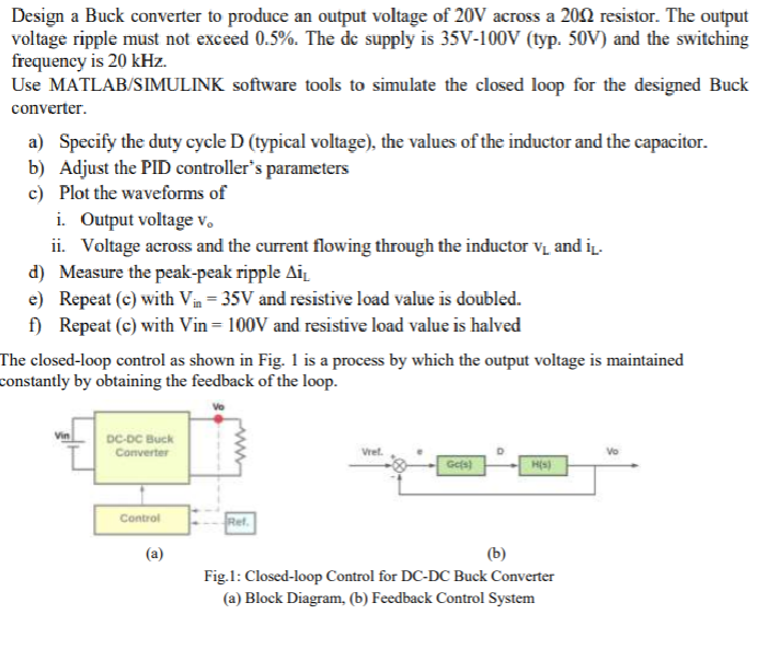
Design a Buck converter to produce an output voltage of 20V across a 2012 resistor. The output voltage ripple must not exceed 0.5%. The dc supply is 35V-100V (typ. 50V) and the switching frequency is 20 kHz. Use MATLAB/SIMULINK software tools to simulate the closed loop for the designed Buck converter. a) Specify the duty cycle D (typical voltage), the values of the inductor and the capacitor. b) Adjust the PID controller's parameters c) Plot the waveforms of i. Output voltage v. ii. Voltage across and the current flowing through the inductor V and iv d) Measure the peak-peak ripple Aiz. e) Repeat (@) with Vin = 35V and resistive load value is doubled. f) Repeat (c) with Vin= 100V and resistive load value is halved The closed-loop control as shown in Fig. 1 is a process by which the output voltage is maintained constantly by obtaining the feedback of the loop. DC-DC Buck Converter Control pret (a) Fig.1: Closed-loop Control for DC-DC Buck Converter (a) Block Diagram, (b) Feedback Control System Design a Buck converter to produce an output voltage of 20V across a 2012 resistor. The output voltage ripple must not exceed 0.5%. The dc supply is 35V-100V (typ. 50V) and the switching frequency is 20 kHz. Use MATLAB/SIMULINK software tools to simulate the closed loop for the designed Buck converter. a) Specify the duty cycle D (typical voltage), the values of the inductor and the capacitor. b) Adjust the PID controller's parameters c) Plot the waveforms of i. Output voltage v. ii. Voltage across and the current flowing through the inductor V and iv d) Measure the peak-peak ripple Aiz. e) Repeat (@) with Vin = 35V and resistive load value is doubled. f) Repeat (c) with Vin= 100V and resistive load value is halved The closed-loop control as shown in Fig. 1 is a process by which the output voltage is maintained constantly by obtaining the feedback of the loop. DC-DC Buck Converter Control pret (a) Fig.1: Closed-loop Control for DC-DC Buck Converter (a) Block Diagram, (b) Feedback Control System
Step by Step Solution
There are 3 Steps involved in it
Step: 1

Get Instant Access to Expert-Tailored Solutions
See step-by-step solutions with expert insights and AI powered tools for academic success
Step: 2

Step: 3

Ace Your Homework with AI
Get the answers you need in no time with our AI-driven, step-by-step assistance
Get Started


