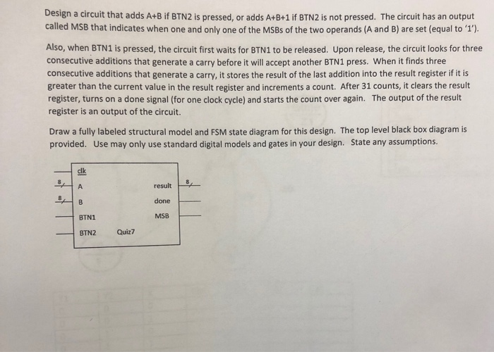
Design a circuit that adds A+B if BTN2 is pressed, or adds A+B+1 if BTN2 is not pressed. The circuit has an output called MSB that indicates when one and only one of the MSBs of the two operands (A and B) are set (equal to '1). Also, when BTN1 is pressed, the circuit first waits for BTN1 to be released. Upon release, the circuit looks for three consecutive additions that generate a carry before it will accept another BTN1 press. When it finds three consecutive additions that generate a carry, it stores the result of the last addition into the result register if it is greater than the current value in the result register and increments a count. After 31 counts, it clears the result register, turns on a done signal (for one clock cycle) and starts the count over again. The output of the result register is an output of the circuit. Draw a fully labeled structural model and FSM state diagram for this design. The top level black box diagram is provided. Use may only use standard digital models and gates in your design. State any assumptions. result done MSB BTN1 BTN2 Quiz7 Design a circuit that adds A+B if BTN2 is pressed, or adds A+B+1 if BTN2 is not pressed. The circuit has an output called MSB that indicates when one and only one of the MSBs of the two operands (A and B) are set (equal to '1). Also, when BTN1 is pressed, the circuit first waits for BTN1 to be released. Upon release, the circuit looks for three consecutive additions that generate a carry before it will accept another BTN1 press. When it finds three consecutive additions that generate a carry, it stores the result of the last addition into the result register if it is greater than the current value in the result register and increments a count. After 31 counts, it clears the result register, turns on a done signal (for one clock cycle) and starts the count over again. The output of the result register is an output of the circuit. Draw a fully labeled structural model and FSM state diagram for this design. The top level black box diagram is provided. Use may only use standard digital models and gates in your design. State any assumptions. result done MSB BTN1 BTN2 Quiz7


