

Question: Design a finite state Moore machine that recognizes a particular pattern: 010. The input to this FSM is a sequence of bits in series coming
Design a finite state Moore machine that recognizes a particular pattern: "010". The input to this FSM is a sequence of bits in series coming in at input M, and the output is a sequence of bits appearing at output R. When the FSM sees "010" as input, it outputs a "1"; otherwise, it should output a "0". In particular, the output R should be "1" in exactly those cycles in which input M has matched the corresponding sequence in the previous 3 cycles. In particular, the FSM detects overlapping sequences of "010". For example: Input Sequence M (starting from left to right) - 000101001011 Output Sequence R (starting from left to right) - 000010100100 Note that the output sequence is delayed by 1 clock cycle compared to the input sequence because the output R is a function of the flip-flop outputs (i.e. the state variables) in a Moore machine. That's why the output sequence becomes 1 in the cycle after "010" has been completed by the input. 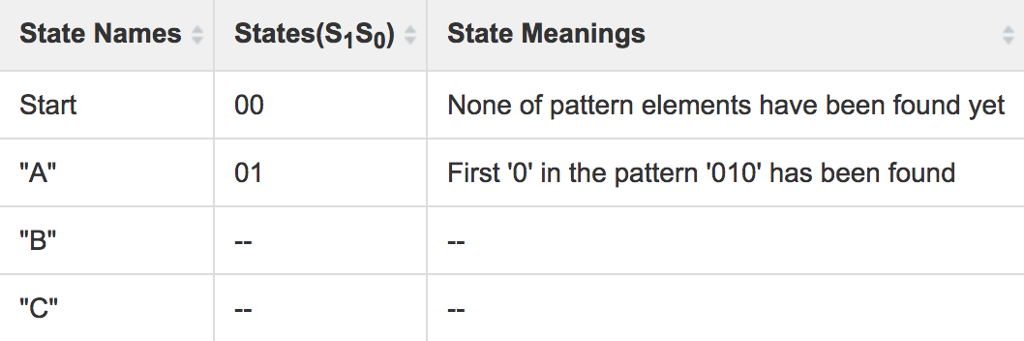 1. Develop an abstract FSM design that solves the problem: include specific input bit values for each transition as well as the output bit in each state. Shown below is an (incomplete) starting point for your FSM. You may assume that your FSM starts in a particular state, but you must tell us which state. Choose a representation for your states and add it to your state transition diagram. Your states should be labeled with state names as well as state bit/output combinations and input bits on transitions. Develop an FSM with the minimum number of states that are necessary. Incomplete FSM for detecting pattern "010": Hint : For your convenience, some of the states and their meanings are shown in the table below, fill the meaning of the remaining states and use it to construct your FSM State Names States(S1S0) State Meanings Start 00 None of pattern elements have been found yet "A" 01 First '0' in the pattern '010' has been found "B" -- -- "C" -- --
2. Fill in K-maps for the next state values S1+, and S0+ based on your FSM.
3. Calculate minimal SOP Boolean logic expressions for the next state values as well as the output R.
4. Implement your design with D flip-flops and gates.
Step by Step Solution
There are 3 Steps involved in it

Get step-by-step solutions from verified subject matter experts