Question
Digital System Could someone please Obtain the Algorithm modeling and RTL modeling of the following task( please read the explanation below) RTL DESIGN METHODLOGY: RTL
Digital System
Could someone please Obtain the Algorithm modeling and RTL modeling of the following task(please read the explanation below)
RTL DESIGN METHODLOGY:
RTL Design Steps
Step 1: (Algorithmic modeling )-specify the desired toplevel
behaviour algorithm thorough flowcharts or pseudo code.
Step 2: (RTL modeling) derive the ASM flowchart or
RTL code (RTL control algorithm) by defining a sequence
of registertransfer operations, such that each operation
can be implemented directly using available design
components.

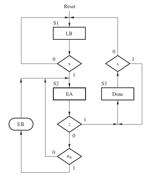
Figure 1 : ASM chart for bit counter circuit
Figure 1 represents the FSM needed for the control circuit.
The FSM has the inputs s, a0, and z and generates the outputs EA, LB, EB, and Done. In-state S1, LB is asserted, so that 0 is loaded in parallel into the counter.
Note that for the control signals, like LB, instead of writing LB = 1, we simply write LB to indicate that the signal is asserted. We assume that external circuitry drives LA to 1 when valid data is present at the parallel inputs of the shift register so that the shift register contents are initialized before s changes to 1.
In-state S2, EA is asserted to cause a shift operation, and the count enable for B is asserted only if a0 = 1.
Design the digital system of this flowchart using Register Transfer Level (RTL) design methodology.
(the steps are given at the beginning of the question.)
Reset S1 LB 0 0 S S S2 S3 EA Done EB 0 0 do Reset S1 LB 0 0 S S S2 S3 EA Done EB 0 0 doStep by Step Solution
There are 3 Steps involved in it
Step: 1

Get Instant Access to Expert-Tailored Solutions
See step-by-step solutions with expert insights and AI powered tools for academic success
Step: 2

Step: 3

Ace Your Homework with AI
Get the answers you need in no time with our AI-driven, step-by-step assistance
Get Started


