Do it hand drawn please.


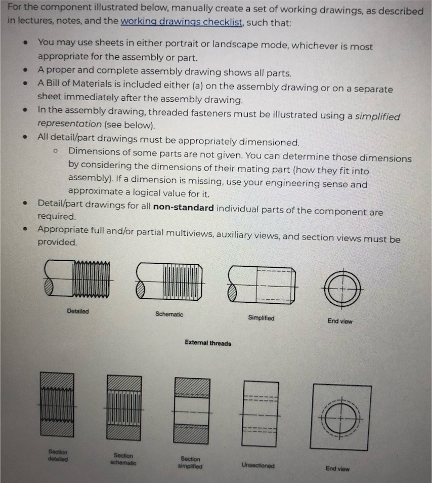
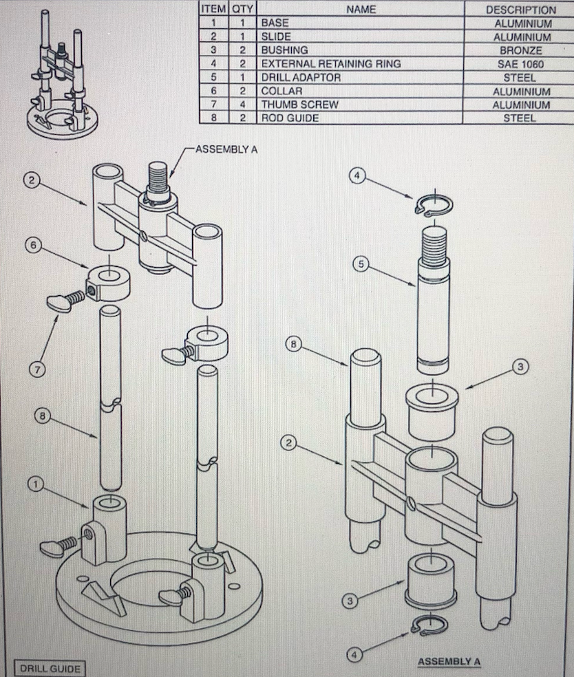
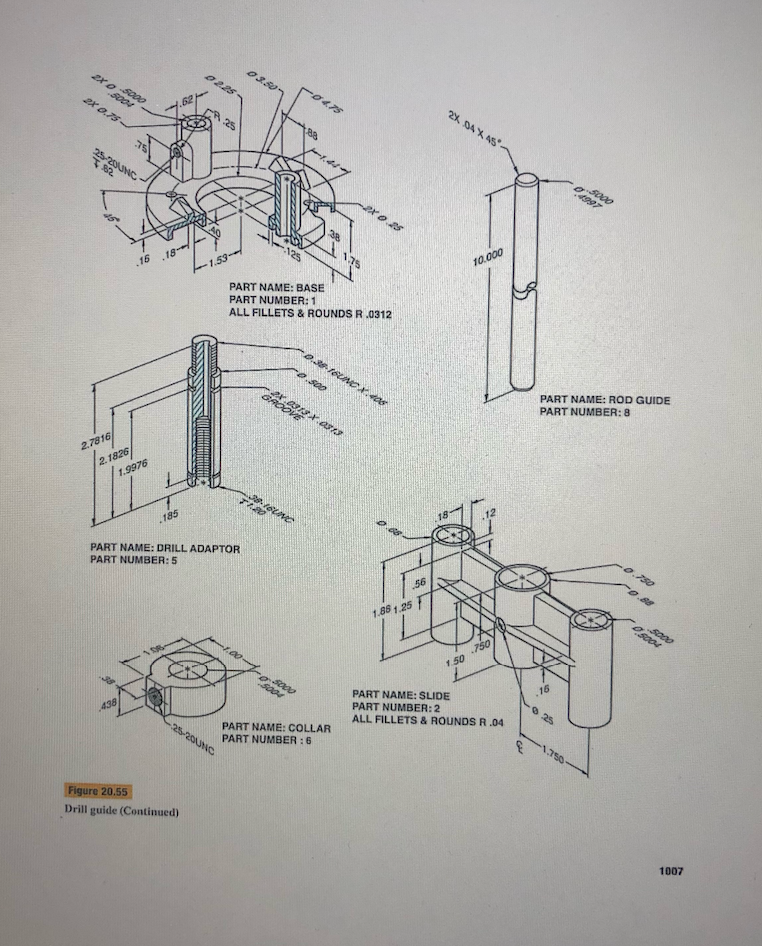
For the component illustrated below, manually create a set of working drawings, as described in lectures, notes, and the working drawings checklist, such that: . . . You may use sheets in either portrait or landscape mode, whichever is most appropriate for the assembly or part. A proper and complete assembly drawing shows all parts. A Bill of Materials is included either (a) on the assembly drawing or on a separate sheet immediately after the assembly drawing. In the assembly drawing, threaded fasteners must be illustrated using a simplified representation (see below). All detail/part drawings must be appropriately dimensioned. Dimensions of some parts are not given. You can determine those dimensions by considering the dimensions of their mating part (how they fit into assembly). If a dimension is missing, use your engineering sense and approximate a logical value for it. Detail/part drawings for all non-standard individual parts of the component are required. Appropriate full and/or partial multiviews, auxiliary views, and section views must be provided O . Detailed Schematic Simplified End view External threads 1 Section detailed Section schematic Section simplified Unsectioned End view ITEM QTY NAME 1 BASE 2 1 SLIDE 3 2 BUSHING 4 2 EXTERNAL RETAINING RING 5 1 DRILL ADAPTOR 6 2. COLLAR 7 4 THUMB SCREW 8 2 ROD GUIDE DESCRIPTION ALUMINIUM ALUMINIUM BRONZE SAE 1060 STEEL ALUMINIUM ALUMINIUM STEEL ASSEMBLY A COS 8 Com ASSEMBLY A DRILL GUIDE 20.500 0225 03.30 2X 0.75 se 2% DAX AS 188 47 25280NC 2. 1997 25 1.75 .16.18-- -1.59 10.000 PART NAME: BASE PART NUMBER: 1 ALL FILLETS & ROUNDS R .0312 -0.3FIOUNCX 445 0.00 2013X 0313 GAROVE PART NAME: ROD GUIDE PART NUMBER: 8 2.7816 2. 1826 1.9976 39.1624 185 PART NAME: DRILL ADAPTOR PART NUMBER: 5 -0.750 -0.0 56 1.86 1.25 OS .750 150 SA . 16 438 PART NAME: SLIDE PART NUMBER: 2 ALL FILLETS & ROUNDS R.04 25 -25-20 PART NAME: COLLAR PART NUMBER : 6 -1790 Figure 20.55 Drill guide (Continued) 1007 For the component illustrated below, manually create a set of working drawings, as described in lectures, notes, and the working drawings checklist, such that: . . . You may use sheets in either portrait or landscape mode, whichever is most appropriate for the assembly or part. A proper and complete assembly drawing shows all parts. A Bill of Materials is included either (a) on the assembly drawing or on a separate sheet immediately after the assembly drawing. In the assembly drawing, threaded fasteners must be illustrated using a simplified representation (see below). All detail/part drawings must be appropriately dimensioned. Dimensions of some parts are not given. You can determine those dimensions by considering the dimensions of their mating part (how they fit into assembly). If a dimension is missing, use your engineering sense and approximate a logical value for it. Detail/part drawings for all non-standard individual parts of the component are required. Appropriate full and/or partial multiviews, auxiliary views, and section views must be provided O . Detailed Schematic Simplified End view External threads 1 Section detailed Section schematic Section simplified Unsectioned End view ITEM QTY NAME 1 BASE 2 1 SLIDE 3 2 BUSHING 4 2 EXTERNAL RETAINING RING 5 1 DRILL ADAPTOR 6 2. COLLAR 7 4 THUMB SCREW 8 2 ROD GUIDE DESCRIPTION ALUMINIUM ALUMINIUM BRONZE SAE 1060 STEEL ALUMINIUM ALUMINIUM STEEL ASSEMBLY A COS 8 Com ASSEMBLY A DRILL GUIDE 20.500 0225 03.30 2X 0.75 se 2% DAX AS 188 47 25280NC 2. 1997 25 1.75 .16.18-- -1.59 10.000 PART NAME: BASE PART NUMBER: 1 ALL FILLETS & ROUNDS R .0312 -0.3FIOUNCX 445 0.00 2013X 0313 GAROVE PART NAME: ROD GUIDE PART NUMBER: 8 2.7816 2. 1826 1.9976 39.1624 185 PART NAME: DRILL ADAPTOR PART NUMBER: 5 -0.750 -0.0 56 1.86 1.25 OS .750 150 SA . 16 438 PART NAME: SLIDE PART NUMBER: 2 ALL FILLETS & ROUNDS R.04 25 -25-20 PART NAME: COLLAR PART NUMBER : 6 -1790 Figure 20.55 Drill guide (Continued) 1007


