Answered step by step
Verified Expert Solution
Question
1 Approved Answer
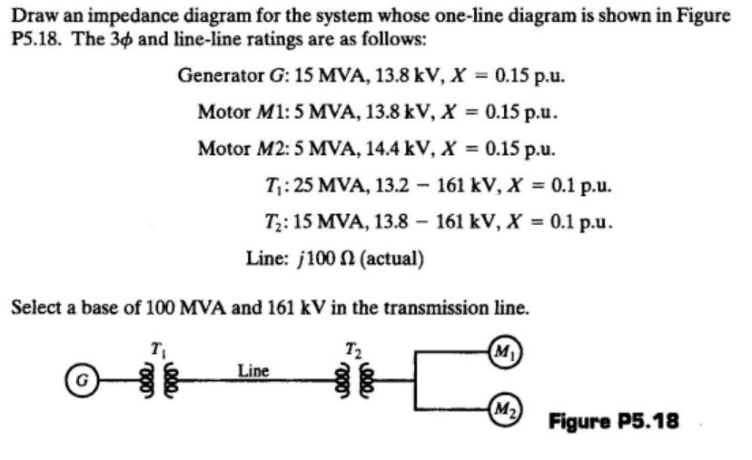
Draw an impedance diagram for the system whose one-line diagram is shown in Figure P5.18. The 30 and line-line ratings are as follows: Generator

Draw an impedance diagram for the system whose one-line diagram is shown in Figure P5.18. The 30 and line-line ratings are as follows: Generator G: 15 MVA, 13.8 kV, X 0.15 p.u. Motor M1: 5 MVA, 13.8 kV, X = 0.15 p.u. %3D Motor M2: 5 MVA, 14.4 kV, X = 0.15 p.u. %3D T:25 MVA, 13.2 161 kV, X = 0.1 p.u. T;: 15 MVA, 13.8 161 kV, X = 0.1 p.u. %3D Line: j100 N (actual) Select a base of 100 MVA and 161 kV in the transmission line. T2 M ) Line G M2 Figure P5.18
Step by Step Solution
★★★★★
3.40 Rating (147 Votes )
There are 3 Steps involved in it
Step: 1

Get Instant Access to Expert-Tailored Solutions
See step-by-step solutions with expert insights and AI powered tools for academic success
Step: 2

Step: 3

Document Format ( 2 attachments)
635daeafbfced_177974.pdf
180 KBs PDF File
635daeafbfced_177974.docx
120 KBs Word File
Ace Your Homework with AI
Get the answers you need in no time with our AI-driven, step-by-step assistance
Get Started


