

Answered step by step
Verified Expert Solution
Question
1 Approved Answer
draw schemetic You are to design, build and test the FSM shown below 0 S/1 M/O 0 The FSM is to be a one-hot implementation.
draw schemetic
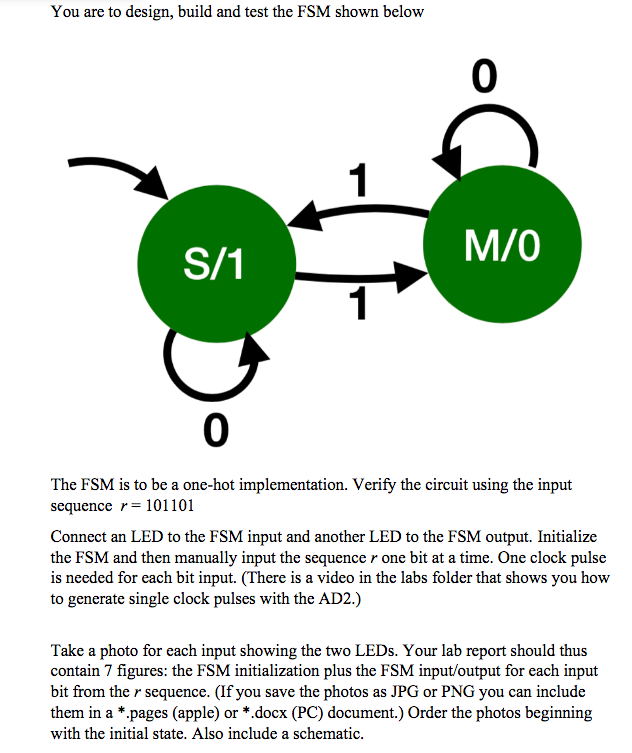
You are to design, build and test the FSM shown below 0 S/1 M/O 0 The FSM is to be a one-hot implementation. Verify the circuit using the input sequence r= 101101 Connect an LED to the FSM input and another LED to the FSM output. Initialize the FSM and then manually input the sequence r one bit at a time. One clock pulse is needed for each bit input. (There is a video in the labs folder that shows you how to generate single clock pulses with the AD2.) Take a photo for each input showing the two LEDs. Your lab report should thus contain 7 figures: the FSM initialization plus the FSM input/output for each input bit from the r sequence. (If you save the photos as JPG or PNG you can include them in a *.pages (apple) or *.docx (PC) document.) Order the photos beginning with the initial state. Also include a schematicStep by Step Solution
There are 3 Steps involved in it
Step: 1

Get Instant Access to Expert-Tailored Solutions
See step-by-step solutions with expert insights and AI powered tools for academic success
Step: 2

Step: 3
Ace Your Homework with AI
Get the answers you need in no time with our AI-driven, step-by-step assistance
Get Started
Advances In Databases And Information Systems 22nd European Conference Adbis 2018 Budapest Hungary September 2 5 2018 Proceedings Lncs 11019
Authors: Andras Benczur ,Bernhard Thalheim ,Tomas Horvath
1st Edition
3319983970, 978-3319983974