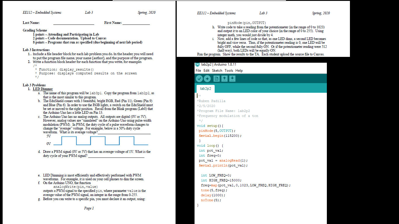
EE112 - Embedded Systems Lab 3 Spring 2020 EE112 - Embedded Systems Lab 3 Spring 2020 Last Name: First Name: Grading Scheme 1 points - Attending and Participating in Lab 2 points - Code documentation. Upload to Canvas 8 points - Programs that run as specified (due beginning of next lab period) pinMode(pin, OUTPUT) h. Write code to take a reading from the potentiometer in the range of 0 to 1023) and output it to an LED color of your choice in the range of 0 to 255). Using integer math you would just divide by 4. i Now, add a few lines of code so that, as one LED dims, a second LED becomes bright and vice versa. Thus, if the potentiometer reading is 0, one LED will be fully OFF, while the second fully ON. Or if the potentiometer reading were 512 (half-way), both LEDs will be each student upload the source file to Canvas. Run the program. Show the results to the TA. Each student upload the source rue to Canvas Lab 3 Instructions 1. Include a file header block for each lab problem you do. In the header, you will need to put the program file name, your name (author), and the purpose of the program 2. Write a function block header for each function that you write, for example: e lab2p2 | Arduino 1.8.11 File Edit Sketch Tools Help * Function: display_results() * Purpose: displays computed results on the screen */ Tab2p2 Lab 3 Problems 1. LED Dimmer a. The name of this program will be lab3pl. Copy the program from lab2p2, as that is the most similar to this program b. The EduShield comes with 3 beautiful, bright RGB, Red Pin 11). Green (Pin 9) and Blue (Pin 6). In order to use the RGB lights, a switch on the EduShield must be set or moved to the right position. Recall from the Blink program (Labo) that the Arduino Uno has a little LED on Pin 13. c. The Arduino Uno has no analog outputs. All outputs are digital (OV or 5V). However, analog values are simulated on the Arduino Uno using pulse-width culation (PWM). In PWM, the duty cycle of a pulse waveform changes to change the "average voltage. For example, below is a 50% duty cycle wavefom. What is its average voltage? 5V *Ruben Padilla *2/5/2020 * Program File Name: lab2p2 Frequency modulation of a ton void setup() { pinMode(5, OUTPUT); Serial.begin(115200); OV d Draw a PWM signal (OV or 5V) that has an average voltage of 1V. What is the duty cycle of your PWM signal? void loop() { int pot_val; int freq=0; pot_val = analogRead(1); Serial.println (pot_val); e LED Dimming is most efficiently and effectively performed with PWM waveforms. For example, it is used on your cell phones to dim the screen. f. On the Arduino UNO, the function analogWrite (pin, value) outputs a PWM signal to the specified pin, where parameter value is the average value of the PWM signal, an integer in the range from 0-255. g. Before you can write to a specific pin you must declare it an output, using int LOW_FREQ=0; int HIGH_FREQ=15000; freq=map (pot_val,0, 1023, LOW_FREQ, HIGH_FREQ); tone (5, freq); delay(1000); noTone (5); Page 1 EE112 - Embedded Systems Lab 3 Spring 2020 EE112 - Embedded Systems Lab 3 Spring 2020 Last Name: First Name: Grading Scheme 1 points - Attending and Participating in Lab 2 points - Code documentation. Upload to Canvas 8 points - Programs that run as specified (due beginning of next lab period) pinMode(pin, OUTPUT) h. Write code to take a reading from the potentiometer in the range of 0 to 1023) and output it to an LED color of your choice in the range of 0 to 255). Using integer math you would just divide by 4. i Now, add a few lines of code so that, as one LED dims, a second LED becomes bright and vice versa. Thus, if the potentiometer reading is 0, one LED will be fully OFF, while the second fully ON. Or if the potentiometer reading were 512 (half-way), both LEDs will be each student upload the source file to Canvas. Run the program. Show the results to the TA. Each student upload the source rue to Canvas Lab 3 Instructions 1. Include a file header block for each lab problem you do. In the header, you will need to put the program file name, your name (author), and the purpose of the program 2. Write a function block header for each function that you write, for example: e lab2p2 | Arduino 1.8.11 File Edit Sketch Tools Help * Function: display_results() * Purpose: displays computed results on the screen */ Tab2p2 Lab 3 Problems 1. LED Dimmer a. The name of this program will be lab3pl. Copy the program from lab2p2, as that is the most similar to this program b. The EduShield comes with 3 beautiful, bright RGB, Red Pin 11). Green (Pin 9) and Blue (Pin 6). In order to use the RGB lights, a switch on the EduShield must be set or moved to the right position. Recall from the Blink program (Labo) that the Arduino Uno has a little LED on Pin 13. c. The Arduino Uno has no analog outputs. All outputs are digital (OV or 5V). However, analog values are simulated on the Arduino Uno using pulse-width culation (PWM). In PWM, the duty cycle of a pulse waveform changes to change the "average voltage. For example, below is a 50% duty cycle wavefom. What is its average voltage? 5V *Ruben Padilla *2/5/2020 * Program File Name: lab2p2 Frequency modulation of a ton void setup() { pinMode(5, OUTPUT); Serial.begin(115200); OV d Draw a PWM signal (OV or 5V) that has an average voltage of 1V. What is the duty cycle of your PWM signal? void loop() { int pot_val; int freq=0; pot_val = analogRead(1); Serial.println (pot_val); e LED Dimming is most efficiently and effectively performed with PWM waveforms. For example, it is used on your cell phones to dim the screen. f. On the Arduino UNO, the function analogWrite (pin, value) outputs a PWM signal to the specified pin, where parameter value is the average value of the PWM signal, an integer in the range from 0-255. g. Before you can write to a specific pin you must declare it an output, using int LOW_FREQ=0; int HIGH_FREQ=15000; freq=map (pot_val,0, 1023, LOW_FREQ, HIGH_FREQ); tone (5, freq); delay(1000); noTone (5); Page 1


