

Answered step by step
Verified Expert Solution
Question
1 Approved Answer
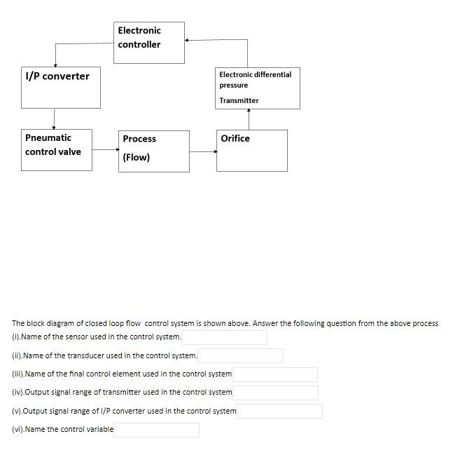
Electronic controller 1/P converter Electronic differential pressure Transmitter Orifice Pneumatic control valve Process (Flow) The block diagram of closed loop flow control system is shown
Step by Step Solution
There are 3 Steps involved in it
Step: 1

Get Instant Access to Expert-Tailored Solutions
See step-by-step solutions with expert insights and AI powered tools for academic success
Step: 2

Step: 3
Ace Your Homework with AI
Get the answers you need in no time with our AI-driven, step-by-step assistance
Get Started
Accounting
Authors: Jonathan E. Duchac, James M. Reeve, Carl S. Warren
23rd Edition
978-0324662962