Answered step by step
Verified Expert Solution
Question
1 Approved Answer
Electronics II Please answer all parts of both question using LTpspice Thank you 3. Working Circuit #3 Simulate the circuit with opposition-mode excitation of Figure
Electronics II
Please answer all parts of both question using LTpspice
Thank you
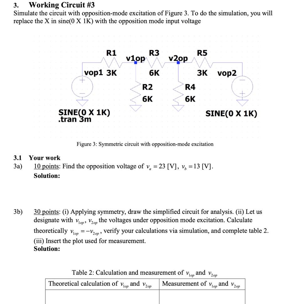
3. Working Circuit #3 Simulate the circuit with opposition-mode excitation of Figure 3. To do the simulation, you will replace the X in sine(0 X 1K) with the opposition mode input voltage R1 R3 R5 vlop v20p vop1 3K 6K 3K vop2 R2 R4 6K 6K SINECO X 1K) .tran 3m SINE(O X 1K) Figure 3: Symmetric circuit with opposition-mode excitation 3.1 3a) Your work 10 points: Find the opposition voltage of v, = 23 [V], v5 = 13 [V]. Solution: 3b) 30 points: (i) Applying symmetry, draw the simplified circuit for analysis. (ii) Let us designate with Vlop, V20p the voltages under opposition mode excitation. Calculate theoretically viop =-V2op, verify your calculations via simulation, and complete table 2. (iii) Insert the plot used for measurement. Solution: Vlop Table 2: Calculation and measurement of Theoretical calculation of Measurement of and V20p and V20p Vlop and V20p Vlop 4. 4a) Conclusion 10 points: Verify that superposition works. Solution: 4b) 10 points: What is the advantage of using superposition this way (i.e., common + opposition modes) when the circuit is symmetrical? Solution: 3. Working Circuit #3 Simulate the circuit with opposition-mode excitation of Figure 3. To do the simulation, you will replace the X in sine(0 X 1K) with the opposition mode input voltage R1 R3 R5 vlop v20p vop1 3K 6K 3K vop2 R2 R4 6K 6K SINECO X 1K) .tran 3m SINE(O X 1K) Figure 3: Symmetric circuit with opposition-mode excitation 3.1 3a) Your work 10 points: Find the opposition voltage of v, = 23 [V], v5 = 13 [V]. Solution: 3b) 30 points: (i) Applying symmetry, draw the simplified circuit for analysis. (ii) Let us designate with Vlop, V20p the voltages under opposition mode excitation. Calculate theoretically viop =-V2op, verify your calculations via simulation, and complete table 2. (iii) Insert the plot used for measurement. Solution: Vlop Table 2: Calculation and measurement of Theoretical calculation of Measurement of and V20p and V20p Vlop and V20p Vlop 4. 4a) Conclusion 10 points: Verify that superposition works. Solution: 4b) 10 points: What is the advantage of using superposition this way (i.e., common + opposition modes) when the circuit is symmetrical? SolutionStep by Step Solution
There are 3 Steps involved in it
Step: 1
Get Instant Access to Expert-Tailored Solutions
See step-by-step solutions with expert insights and AI powered tools for academic success
Step: 2
Step: 3
Ace Your Homework with AI
Get the answers you need in no time with our AI-driven, step-by-step assistance
Get Started