Answered step by step
Verified Expert Solution
Question
1 Approved Answer
Enter the IPv4 Subnet information for all lab subnets into Table #1a below. Table #1a: IPv4 Subnet Design Subnet Name Subnet A Subnet B
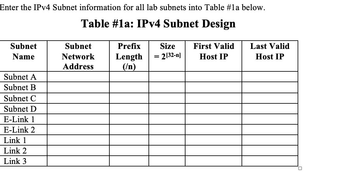
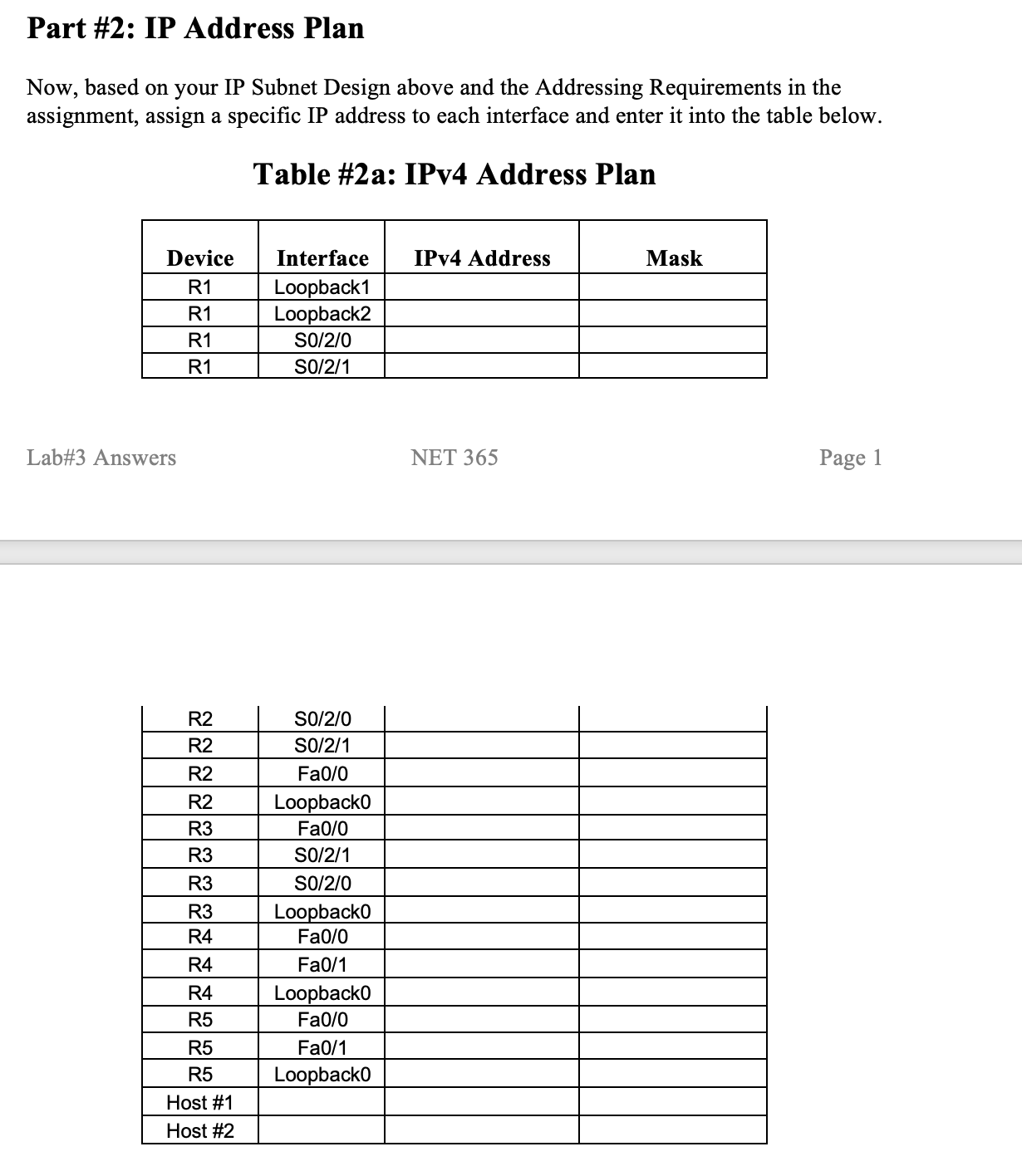
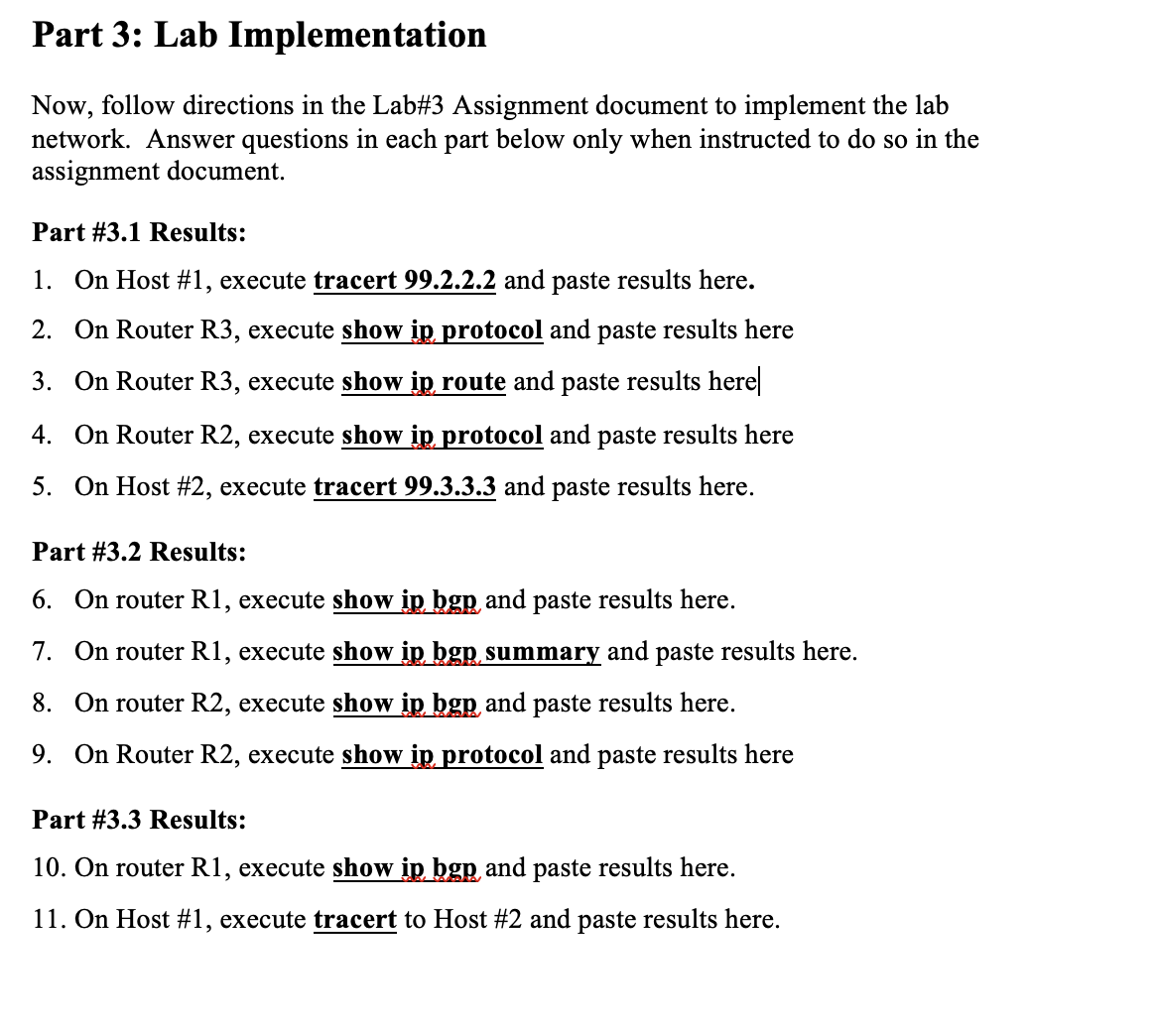
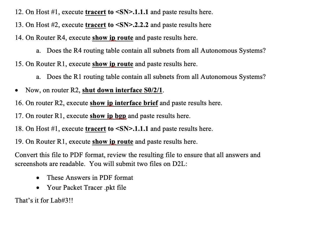
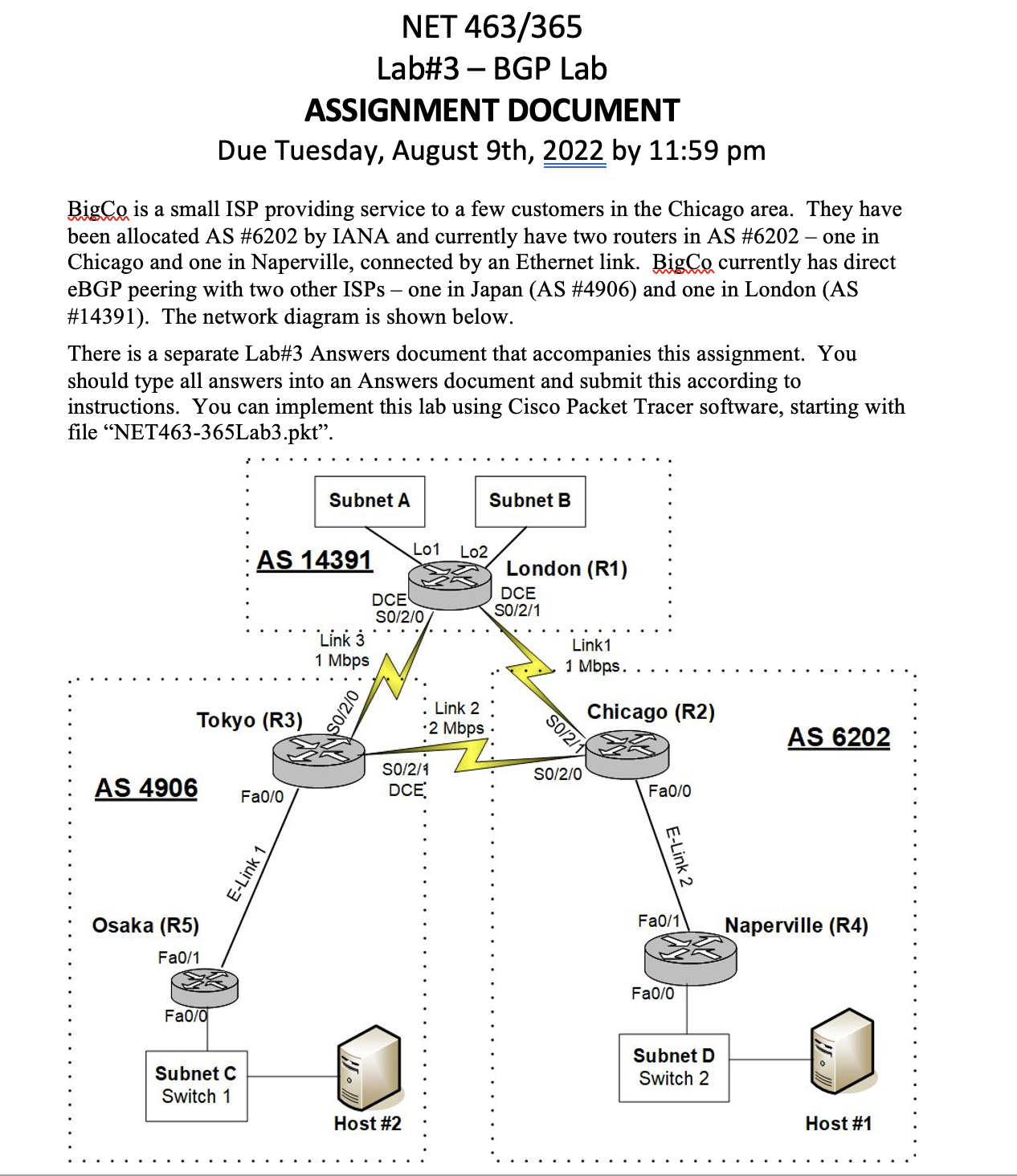
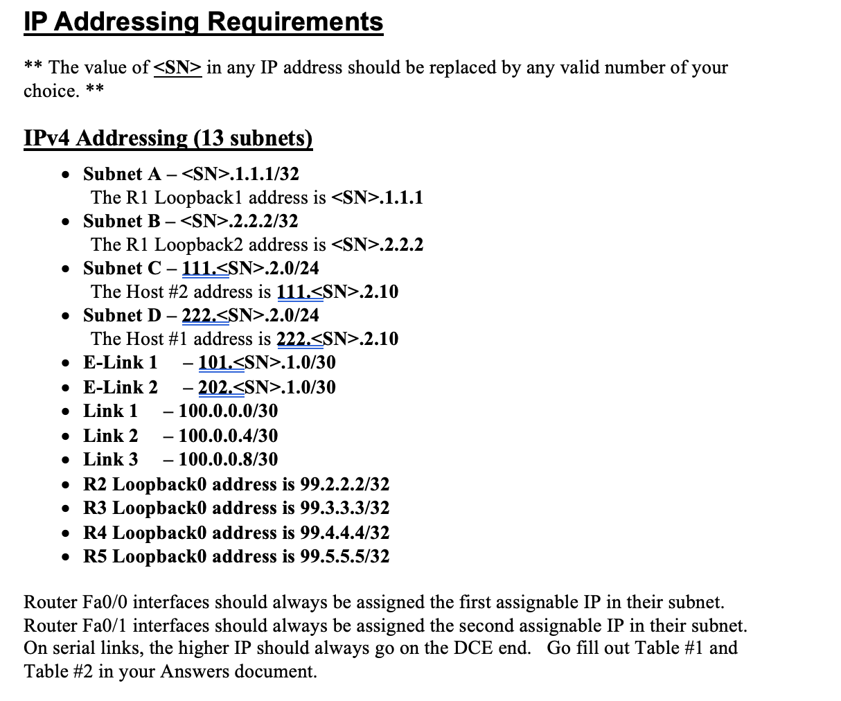
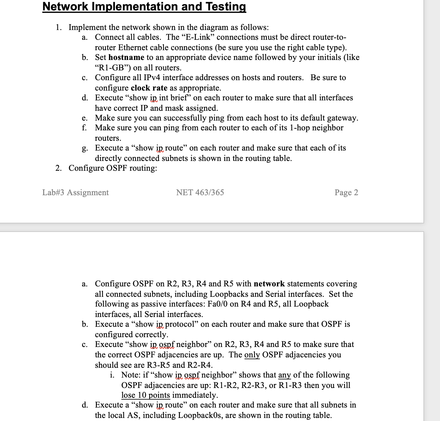
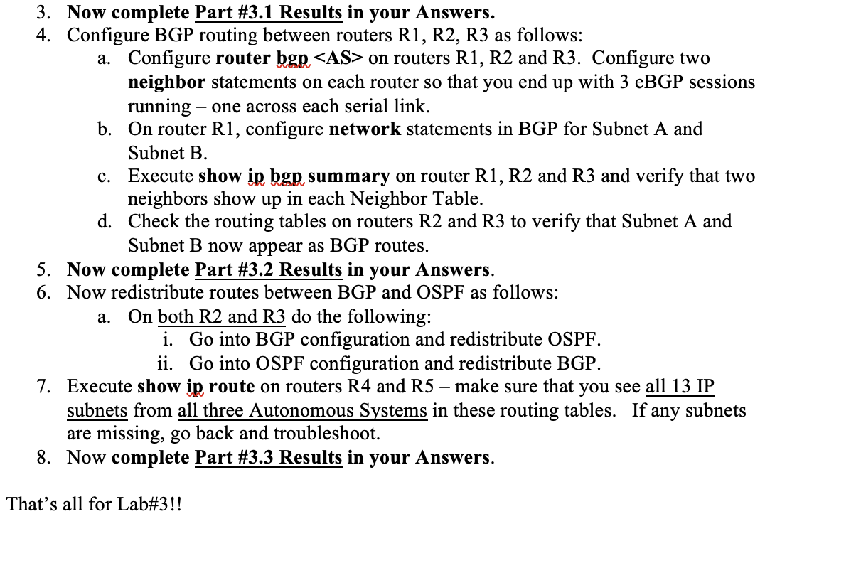
Enter the IPv4 Subnet information for all lab subnets into Table #1a below. Table #1a: IPv4 Subnet Design Subnet Name Subnet A Subnet B Subnet C Subnet D E-Link 1 E-Link 2 Link 1 Link 2 Link 3 Subnet Network Address Prefix Length (/n) Size = 2[32-n] First Valid Host IP Last Valid Host IP Part #2: IP Address Plan Now, based on your IP Subnet Design above and the Addressing Requirements in the assignment, assign a specific IP address to each interface and enter it into the table below. Table #2a: IPv4 Address Plan Device R1 R1 R1 R1 Lab#3 Answers R2 R2 R2 R2 R3 R3 R3 R3 R4 R4 R4 R5 R5 R5 Host #1 Host #2 Interface IPv4 Address Loopback1 Loopback2 SO/2/0 SO/2/1 SO/2/0 S0/2/1 Fa0/0 Loopback0 Fa0/0 SO/2/1 SO/2/0 Loopback0 Fa0/0 Fa0/1 Loopback0 Fa0/0 Fa0/1 Loopback0 NET 365 Mask Page 1 Part 3: Lab Implementation Now, follow directions in the Lab#3 Assignment document to implement the lab network. Answer questions in each part below only when instructed to do so in the assignment document. Part # 3.1 Results: 1. On Host #1, execute tracert 99.2.2.2 and paste results here. 2. On Router R3, execute show ip protocol and paste results here 3. On Router R3, execute show ip route and paste results here 4. On Router R2, execute show ip protocol and paste results here 5. On Host #2, execute tracert 99.3.3.3 and paste results here. Part # 3.2 Results: 6. On router R1, execute show ip bgp and paste results here. 7. On router R1, execute show ip bgp summary and paste results here. 8. On router R2, execute show ip bgp and paste results here. 9. On Router R2, execute show ip protocol and paste results here Part # 3.3 Results: 10. On router R1, execute sho ip bgp and paste results here. 11. On Host #1, execute tracert to Host #2 and paste results here. 12. On Host #1, execute tracert to .1.1.1 and paste results here. 13. On Host #2, execute tracert to .2.2.2 and paste results here 14. On Router R4, execute show ip route and paste results here. a. Does the R4 routing table contain all subnets from all Autonomous Systems? 15. On Router R1, execute show ip route and paste results here. a. Does the R1 routing table contain all subnets from all Autonomous Systems? Now, on router R2, shut down interface S0/2/1. 16. On router R2, execute show ip interface brief and paste results here. 17. On router R1, execute show ip bgp and paste results here. 18. On Host #1, execute tracert to .1.1.1 and paste results here. 19. On Router R1, execute show ip route and paste results here. Convert this file to PDF format, review the resulting file to ensure that all answers and screenshots are readable. You will submit two files on D2L: These Answers in PDF format Your Packet Tracer .pkt file That's it for Lab#3!! BigCo is a small ISP providing service to a few customers in the Chicago area. They have been allocated AS #6202 by IANA and currently have two routers in AS #6202 - one in Chicago and one in Naperville, connected by an Ethernet link. BigCo currently has direct eBGP peering with two other ISPs - one in Japan (AS #4906) and one in London (AS #14391). The network diagram is shown below. There is a separate Lab#3 Answers document that accompanies this assignment. You should type all answers into an Answers document and submit this according to instructions. You can implement this lab using Cisco Packet Tracer software, starting with file "NET463-365Lab3.pkt". AS 4906 NET 463/365 Lab#3 - BGP Lab ASSIGNMENT DOCUMENT Due Tuesday, August 9th, 2022 by 11:59 pm Osaka (R5) Fa0/1 Tokyo (R3) Fa0/0 Subnet C Switch 1 AS 14391 Fa0/0 Subnet A E-Link 1 Link 3 1 Mbps S0/2/0 DCE SO/2/0 Lo1 Lo2 Host #2 Link 2 -2 Mbps SO/2/1 DCE Subnet B London (R1) DCE SO/2/1 Link1 1 Mbps. S0/2/1 Chicago (R2) SO/2/0 Fa0/0 E-Link 2 Fa0/1 Fa0/0 Subnet D Switch 2 AS 6202 Naperville (R4) Host #1 IP Addressing Requirements ** The value of in any IP address should be replaced by any valid number of your choice. ** IPv4 Addressing (13 subnets) Subnet A - .1.1.1/32 The R1 Loopback1 address is .1.1.1 Subnet B - .2.2.2/32 The R1 Loopback2 address is .2.2.2 Subnet C - 111. .2.0/24 The Host #2 address is 111. .2.10 Subnet D - 222. .2.0/24 The Host #1 address is 222. .2.10 101. .1.0/30 E-Link 1 E-Link 2 202. .1.0/30 Link 1 Link 2 Link 3 - - 100.0.0.0/30 - 100.0.0.4/30 - 100.0.0.8/30 R2 Loopback0 address is 99.2.2.2/32 R3 Loopback0 address is 99.3.3.3/32 R4 Loopback0 address is 99.4.4.4/32 R5 Loopback0 address is 99.5.5.5/32 Router Fa0/0 interfaces should always be assigned the first assignable IP in their subnet. Router Fa0/1 interfaces should always be assigned the second assignable IP in their subnet. On serial links, the higher IP should always go on the DCE end. Go fill out Table #1 and Table #2 in your Answers document. Network Implementation and Testing 1. Implement the network shown in the diagram as follows: a. Connect all cables. The "E-Link" connections must be direct router-to- router Ethernet cable connections (be sure you use the right cable type). Set hostname to an appropriate device name followed by your initials (like "R1-GB") on all routers. b. c. Configure all IPv4 interface addresses on hosts and routers. Be sure to configure clock rate as appropriate. d. Execute "show ip int brief" on each router to make sure that all interfaces have correct IP and mask assigned. Make sure you can successfully ping from each host to its default gateway. Make sure you can ping from each router to each of its 1-hop neighbor e. f. routers. g. Execute a "show ip route" on each router and make sure that each of its directly connected subnets is shown in the routing table. 2. Configure OSPF routing: Lab#3 Assignment NET 463/365 Page 2 a. Configure OSPF on R2, R3, R4 and R5 with network statements covering all connected subnets, including Loopbacks and Serial interfaces. Set the following as passive interfaces: Fa0/0 on R4 and R5, all Loopback interfaces, all Serial interfaces. b. Execute a "show ip protocol" on each router and make sure that OSPF is configured correctly. c. Execute "show ip, ospf neighbor" on R2, R3, R4 and R5 to make sure that the correct OSPF adjacencies are up. The only OSPF adjacencies you should see are R3-R5 and R2-R4. i. Note: if "show ip ospf neighbor" shows that any of the following OSPF adjacencies are up: R1-R2, R2-R3, or R1-R3 then you will lose 10 points immediately. d. Execute a "show ip route" on each router and make sure that all subnets in the local AS, including Loopback0s, are shown in the routing table. 3. Now complete Part # 3.1 Results in your Answers. 4. Configure BGP routing between routers R1, R2, R3 as follows: a. Configure router bgp on routers R1, R2 and R3. Configure two neighbor statements on each router so that you end up with 3 eBGP sessions running - one across each serial link. b. On router R1, configure network statements in BGP for Subnet A and Subnet B. c. Execute show ip bgp summary on router R1, R2 and R3 and verify that two neighbors show up in each Neighbor Table. d. Check the routing tables on routers R2 and R3 to verify that Subnet A and Subnet B now appear as BGP routes. 5. Now complete Part # 3.2 Results in your Answers. 6. Now redistribute routes between BGP and OSPF as follows: a. On both R2 and R3 do the following: i. Go into BGP configuration and redistribute OSPF. ii. Go into OSPF configuration and redistribute BGP. 7. Execute show ip route on routers R4 and R5 make sure that you see all 13 IP subnets from all three Autonomous Systems in these routing tables. If any subnets are missing, go back and troubleshoot. 8. Now complete Part # 3.3 Results in your Answers. That's all for Lab#3!!
Step by Step Solution
There are 3 Steps involved in it
Step: 1

Get Instant Access to Expert-Tailored Solutions
See step-by-step solutions with expert insights and AI powered tools for academic success
Step: 2

Step: 3

Ace Your Homework with AI
Get the answers you need in no time with our AI-driven, step-by-step assistance
Get Started


