Answered step by step
Verified Expert Solution
Question
1 Approved Answer
Ethylene and chlorine ( streams 1 and 2 ) are fed in stoichiometric amounts at 2 5 C and 1 atm to a 1 .
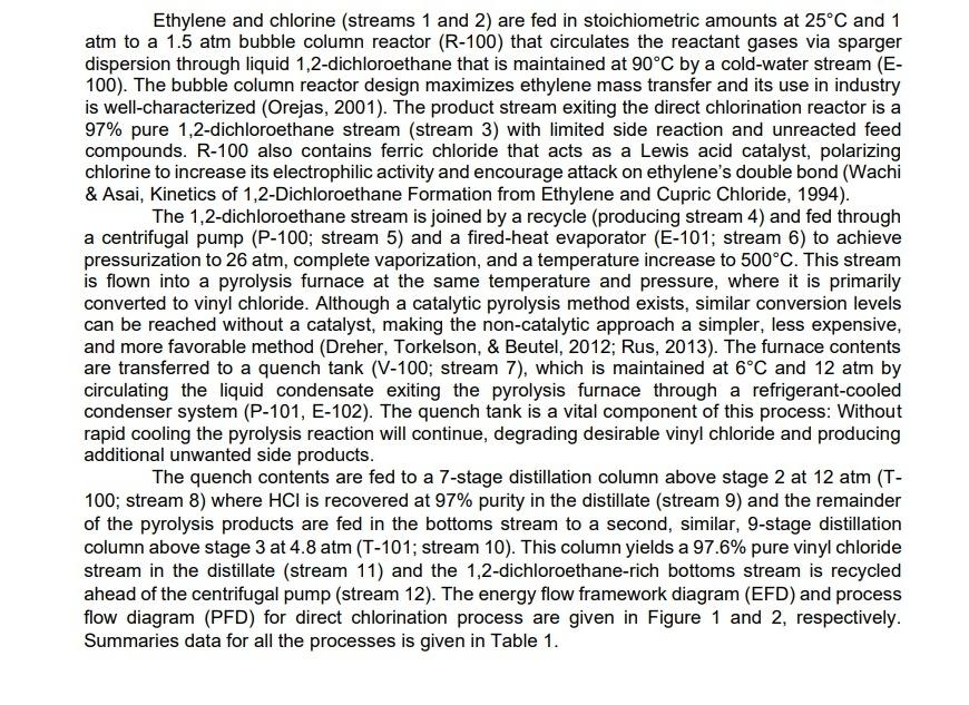
Ethylene and chlorine streams and are fed in stoichiometric amounts at and atm to a atm bubble column reactor that circulates the reactant gases via sparger dispersion through liquid dichloroethane that is maintained at by a coldwater stream E The bubble column reactor design maximizes ethylene mass transfer and its use in industry is wellcharacterized Orejas The product stream exiting the direct chlorination reactor is a pure dichloroethane stream stream with limited side reaction and unreacted feed compounds. R also contains ferric chloride that acts as a Lewis acid catalyst, polarizing chlorine to increase its electrophilic activity and encourage attack on ethylene's double bond Wachi & Asai, Kinetics of Dichloroethane Formation from Ethylene and Cupric Chloride,
The dichloroethane stream is joined by a recycle producing stream and fed through a centrifugal pump P; stream and a firedheat evaporator E; stream to achieve pressurization to atm, complete vaporization, and a temperature increase to This stream is flown into a pyrolysis furnace at the same temperature and pressure, where it is primarily converted to vinyl chloride. Although a catalytic pyrolysis method exists, similar conversion levels can be reached without a catalyst, making the noncatalytic approach a simpler, less expensive, and more favorable method Dreher Torkelson, & Beutel, ; Rus, The furnace contents are transferred to a quench tank ; stream which is maintained at and atm by circulating the liquid condensate exiting the pyrolysis furnace through a refrigerantcooled condenser system P E The quench tank is a vital component of this process: Without rapid cooling the pyrolysis reaction will continue, degrading desirable vinyl chloride and producing additional unwanted side products.
The quench contents are fed to a stage distillation column above stage at atm T ; stream where is recovered at purity in the distillate stream and the remainder of the pyrolysis products are fed in the bottoms stream to a second, similar, stage distillation column above stage at atm T; stream This column yields a pure vinyl chloride stream in the distillate stream and the dichloroethanerich bottoms stream is recycled ahead of the centrifugal pump stream The energy flow framework diagram EFD and process flow diagram PFD for direct chlorination process are given in Figure and respectively. Summaries data for all the processes is given in Table

Step by Step Solution
There are 3 Steps involved in it
Step: 1

Get Instant Access to Expert-Tailored Solutions
See step-by-step solutions with expert insights and AI powered tools for academic success
Step: 2

Step: 3

Ace Your Homework with AI
Get the answers you need in no time with our AI-driven, step-by-step assistance
Get Started


