

Answered step by step
Verified Expert Solution
Question
1 Approved Answer
excess-3 code to binary code by subtracting the excess- 3 code with 3 and then convert the resulting binary to gray code with simple logic
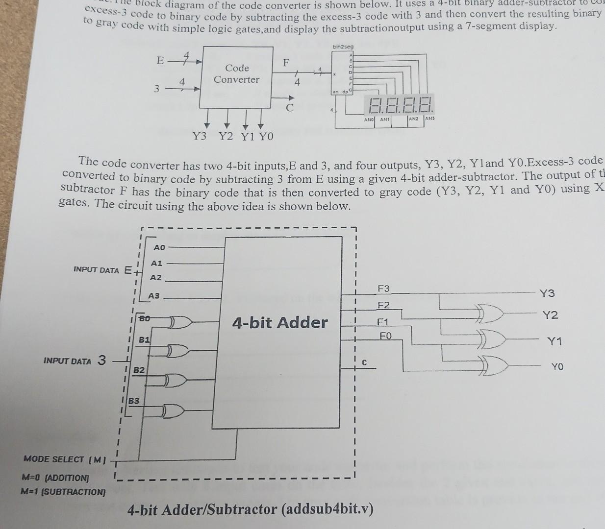
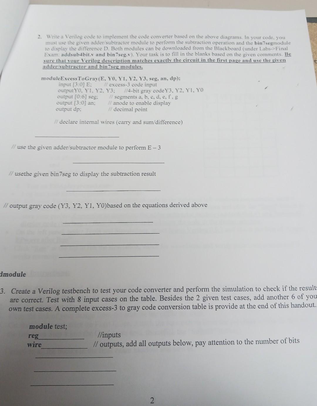
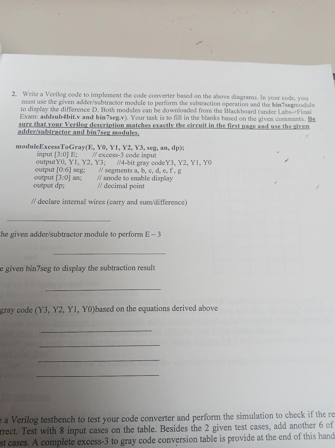
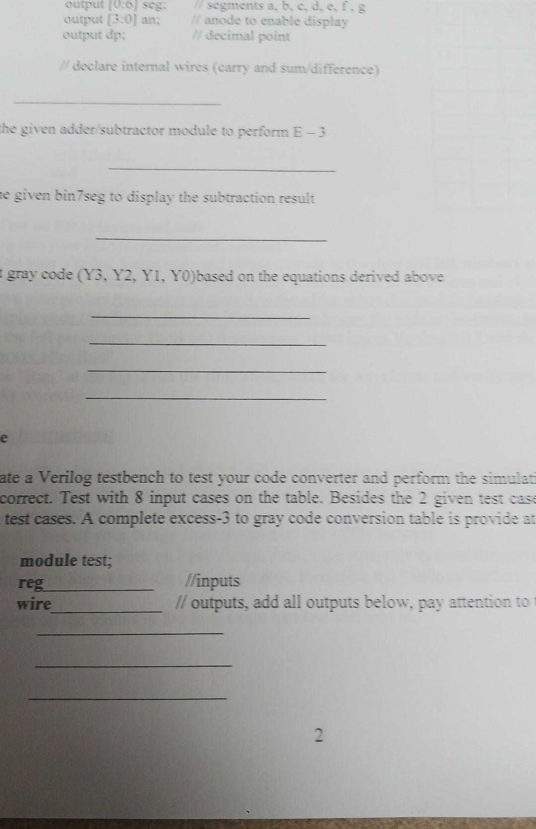
excess-3 code to binary code by subtracting the excess- 3 code with 3 and then convert the resulting binary to gray code with simple logic gates, and display the subtractionoutput using a 7-segment display. The code converter has two 4-bit inputs, E and 3, and four outputs, Y3, Y2, Y1and Y0.Excess-3 code converted to binary code by subtracting 3 from E using a given 4-bit adder-subtractor. The output of t subtractor F has the binary code that is then converted to gray code (Y3, Y2, Y1 and Y0) using gates. The circuit using the above idea is shown below. 4-bit Adder/Subtractor (addsub4bit.v) Create a Verilog testbench to test your code converter and perform the simulation to check if the result are correct. Test with 8 input cases on the table. Besides the 2 given test cases, add another 6 of you own test cases. A complete excess- 3 to gray code conversion table is provide at the end of this handout module test; reg //inputs wire // outputs, add all outputs below, pay attention to the number of bits 2. Write a Verilog code to implement the code converter based on the above diagrams. In your code, you must use the given adder/subtractor module to perform the subtraction operation and the bin7segmodule to display the difference D. Both modules can be downloaded from the Blackboard (under Labs->Final Exam: addsub4bit.v and bin7seg.v). Your task is to fill in the blanks based on the given comments. Be sure that your Verilog description matches exactly the circuit in the first page and use the given adder/subtractor and bin 7 seg modules. moduleExcessToGray(E, Y0, Y1, Y2, Y3, seg, an, dp); input[3:0]E;output0,Y1,Y2,Y3;//4bitgraycodeY3,Y2,Y1,Y0//excess-3codeinput output[0:6]seg;output[3:0]an;outputdp;//segmentsa,b,c,d,e,f,g//anodetoenabledisplay//decimalpoint // declare internal wires (carry and sum/difference) he given adder/subtractor module to perform E3 given bin7seg to display the subtraction result gray code (Y3,Y2,Y1,Y0) based on the equations derived above a Verilog testbench to test your code converter and perform the simulation to check if the rrect. Test with 8 input cases on the table. Besides the 2 given test cases, add another 6 of st cases. A complete excess-3 to gray code conversion table is provide at the end of this hand declare internal wires (carry and sum/difference) he given adder/subtractor module to perform E3 given bin7seg to display the subtraction result gray code (Y3, Y2, Y1, YO) based on the equations derived above ate a Verilog testbench to test your code converter and perform the simulat correct. Test with 8 input cases on the table. Besides the 2 given test casi test cases. A complete excess-3 to gray code conversion table is provide at: module test; reg /inputs wire // outputs, add all outputs below, pay attention to
Step by Step Solution
There are 3 Steps involved in it
Step: 1

Get Instant Access to Expert-Tailored Solutions
See step-by-step solutions with expert insights and AI powered tools for academic success
Step: 2

Step: 3
Ace Your Homework with AI
Get the answers you need in no time with our AI-driven, step-by-step assistance
Get Started
A Complete Guide To Data Science Essentials
Authors: Miguel
1st Edition
9358684992, 978-9358684995