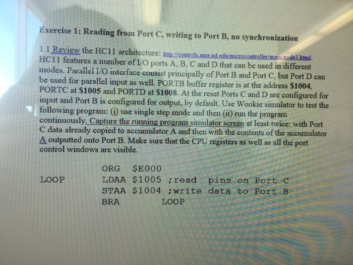
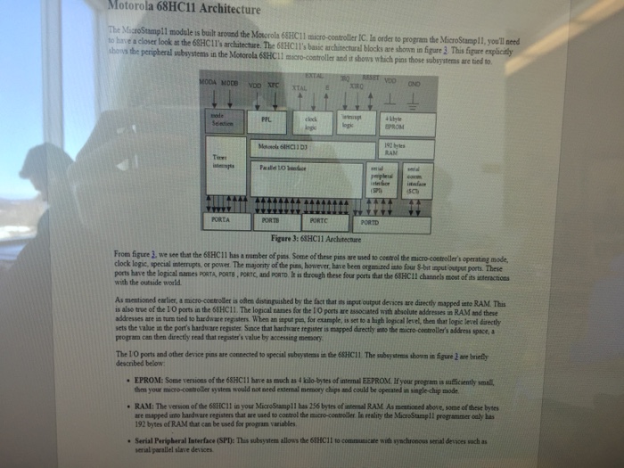
Exercise 1: Reading from Port C, writing to Port B, no synchronization 1.1 Review the HC11 architecture: itp:/icontrols ame.nd edu/microcontroller/main node3 html. HC11 features a number ofI/O ports A, B, C and D that can be used in different modes. Parallel I/O interface consist principally of Port B and Port C, but Port D can be used for parallel PORTC at $1005 and PORTD at $1008. At the reset Ports C and D are configured for input and Port B is configured for output, by default. Use Wookie simulator to test the following program: () use single step mode and then (ii) run the program continuously. Capture the running program simulator screen at least twice: with Port C data already copied to accumulator A and then with the contents of the accumulator A outputted onto Port B. Make sure that the CPU registers as well as all the port control windows are visible. inp ut as well. PORTB buffer register is at the address $1004 ORG $E000 LDAA $1005 read pins on Port c STAA $1004 write data to Port B BRA LOOP LOOP Exercise 1: Reading from Port C, writing to Port B, no synchronization 1.1 Review the HC11 architecture: itp:/icontrols ame.nd edu/microcontroller/main node3 html. HC11 features a number ofI/O ports A, B, C and D that can be used in different modes. Parallel I/O interface consist principally of Port B and Port C, but Port D can be used for parallel PORTC at $1005 and PORTD at $1008. At the reset Ports C and D are configured for input and Port B is configured for output, by default. Use Wookie simulator to test the following program: () use single step mode and then (ii) run the program continuously. Capture the running program simulator screen at least twice: with Port C data already copied to accumulator A and then with the contents of the accumulator A outputted onto Port B. Make sure that the CPU registers as well as all the port control windows are visible. inp ut as well. PORTB buffer register is at the address $1004 ORG $E000 LDAA $1005 read pins on Port c STAA $1004 write data to Port B BRA LOOP LOOP