Answered step by step
Verified Expert Solution
Question
1 Approved Answer
Exercise 4 Goal: Mastering the basics of an ALU. Task 1. Complete the truth table of the following demultiplexer circuit (see Figure 1): a) Which
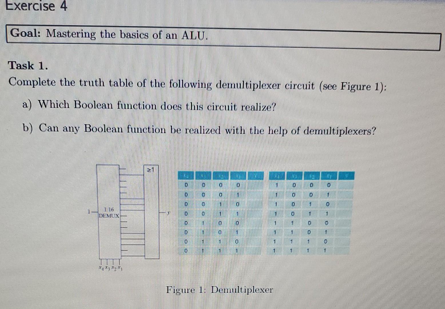
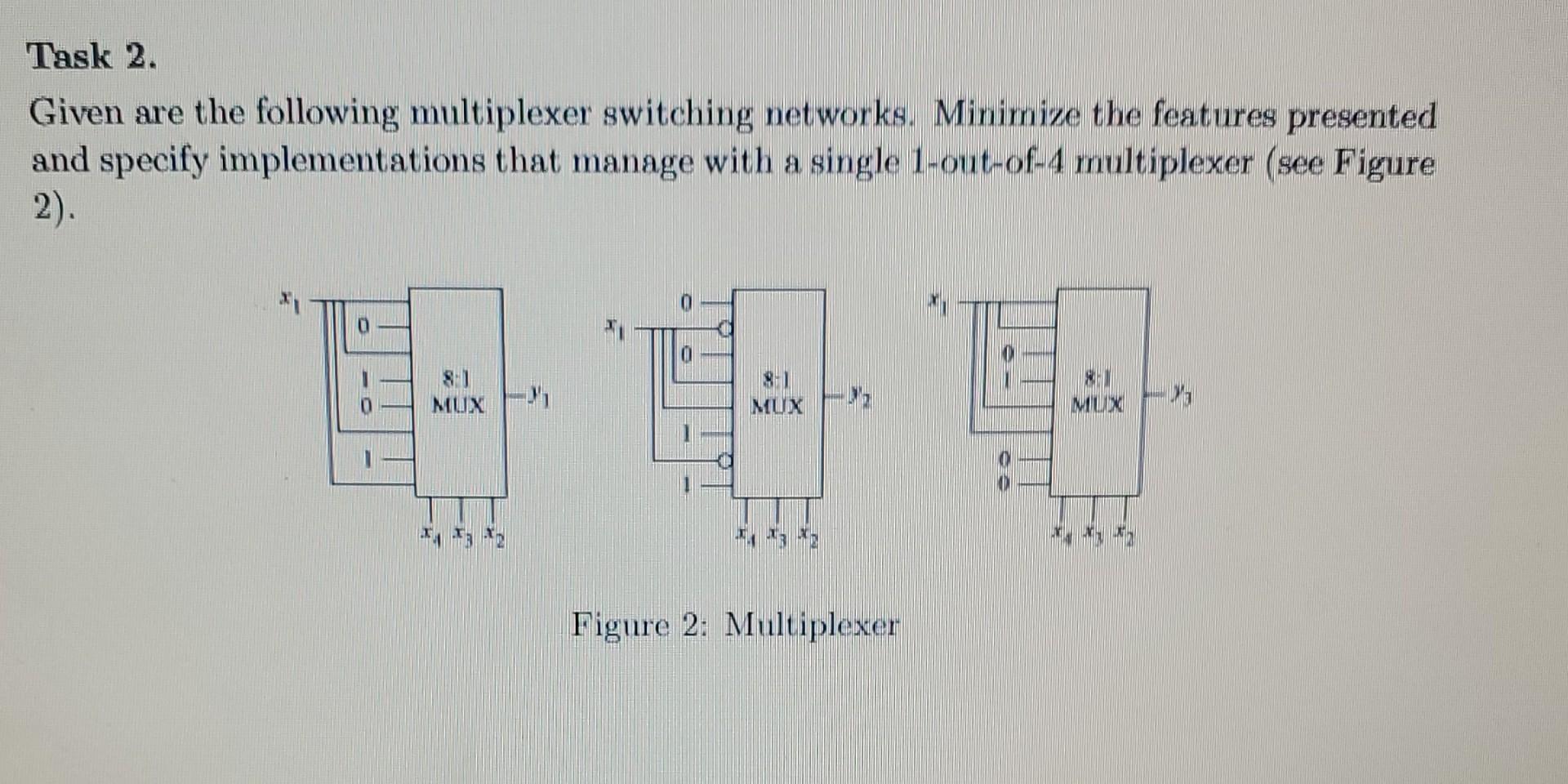
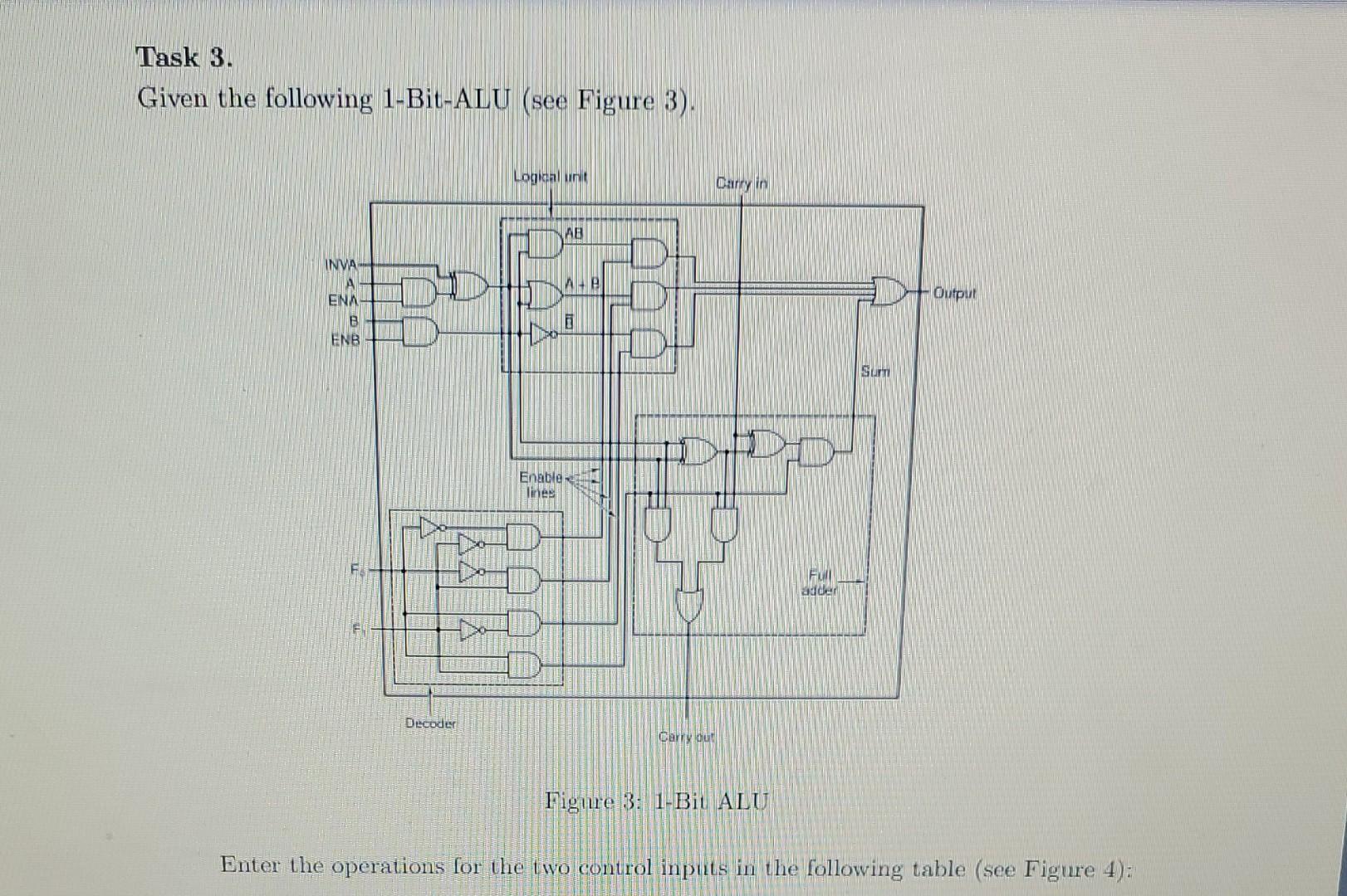
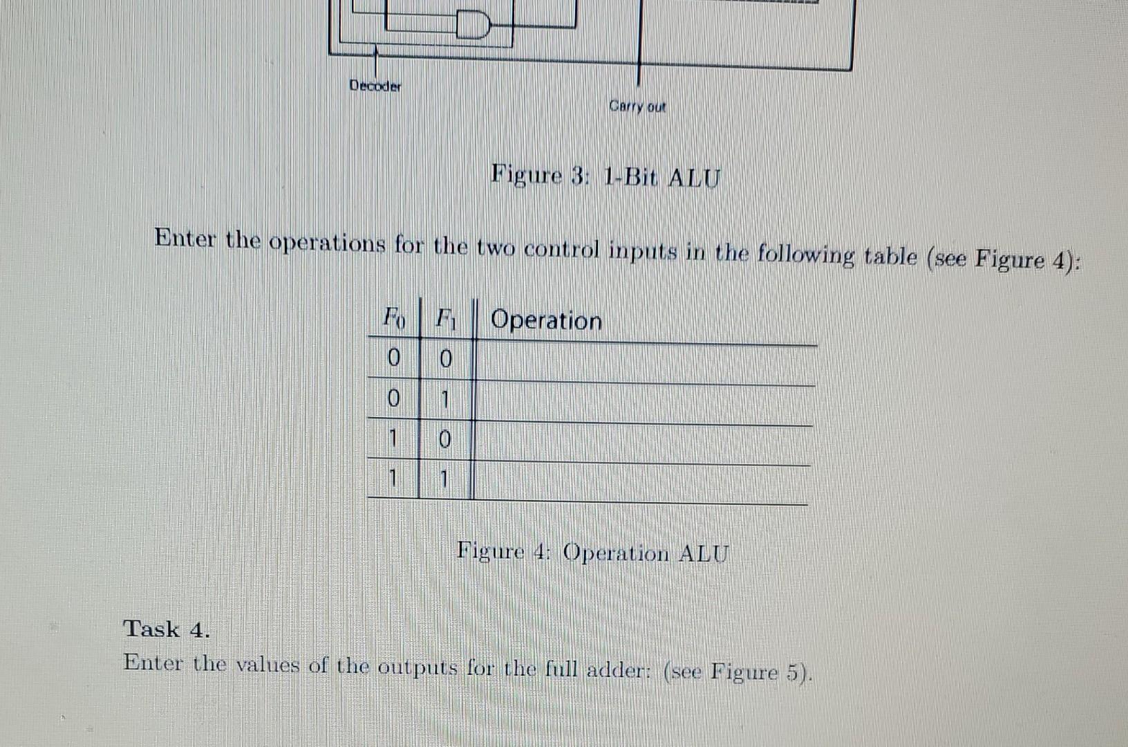
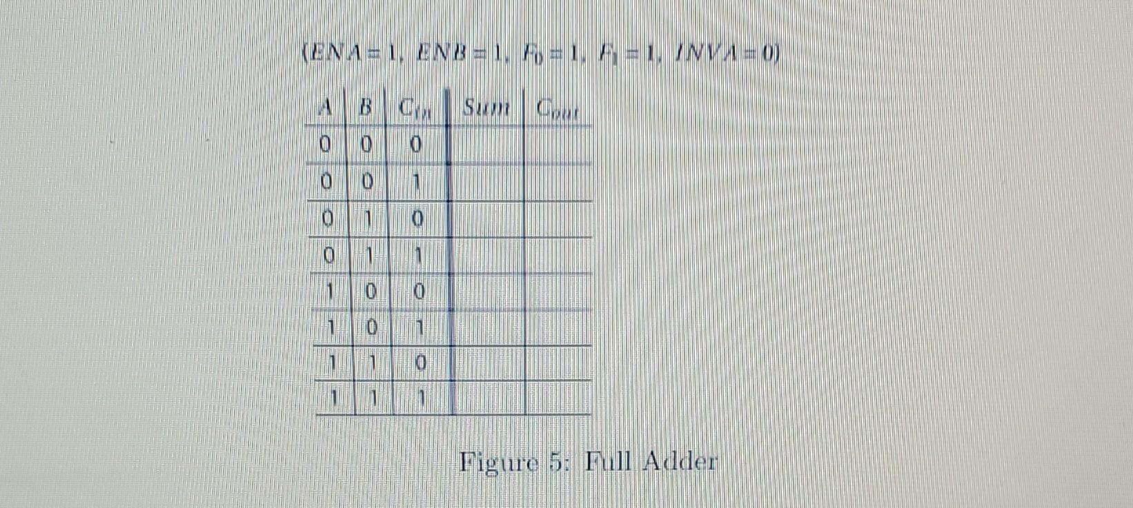
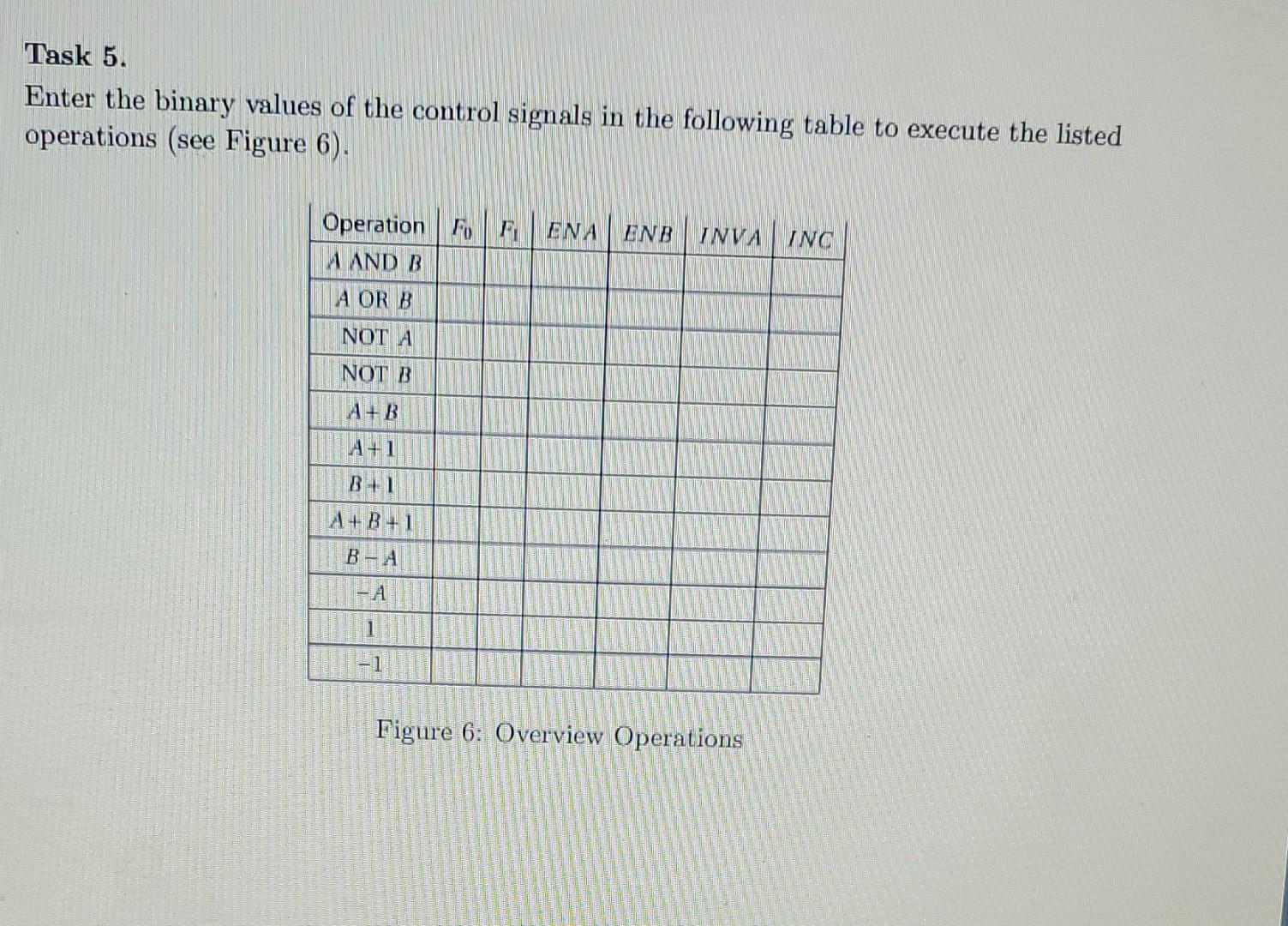
Exercise 4 Goal: Mastering the basics of an ALU. Task 1. Complete the truth table of the following demultiplexer circuit (see Figure 1): a) Which Boolean function does this circuit realize? b) Can any Boolean function be realized with the help of demultiplexers? MAN 10 0 0 01 0 0 1 0 In MENUN 10 0 10 1 11 0 D 1 0 Figure 1: Demultiplexer Task 2. Given are the following multiplexer switching networks. Minimize the features presented and specify implementations that manage with a single 1-out-of-4 multiplexer (see Figure 2). 0 0 MUX 2 MUX MILIKI 1 Figure 2: Multiplexer Task 3. Given the following 1-Bit-ALU (see Figure 3). Logical Carry in AB Ae INVA A ENN B 090 Output ENB Sum PD Enable Full weder Decoder Camry out Figure 3: 1-Bit ALU Enter the operations for the two control inputs in the following table (see Figure 4): Decoder Carry out Figure 3: 1-Bit ALU Enter the operations for the two control inputs in the following table (see Figure 4): Operation 0 0 0 1 1 0 D 1 1 Figure 4: Operation ALU Task 4. Enter the values of the outputs for the full adder: (see Figure 5). KENAL. ENBal al IV01 B CW SUPER 0 MO 10 1 O 0 1 0 1 10 Figlie 5: Full Adder Task 5. Enter the binary values of the control signals in the following table to execute the listed operations (see Figure 6). Operation F F A AND B ENA ENB INVA INC A OR B NOT A NOT B A+B A+1 A+B+1 A 1 Figure 6: Overview Operations
Step by Step Solution
There are 3 Steps involved in it
Step: 1

Get Instant Access to Expert-Tailored Solutions
See step-by-step solutions with expert insights and AI powered tools for academic success
Step: 2

Step: 3

Ace Your Homework with AI
Get the answers you need in no time with our AI-driven, step-by-step assistance
Get Started


