Answered step by step
Verified Expert Solution
Question
1 Approved Answer
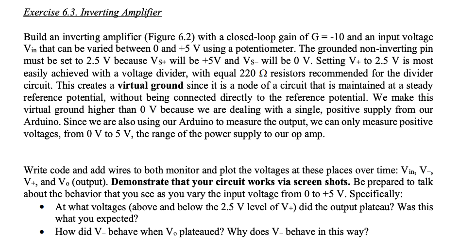
Exercise 6.3. Inverting Amplifier Build an inverting amplifier (Figure 6.2) with a closed-loop gain of G = -10 and an input voltage Vin that

Exercise 6.3. Inverting Amplifier Build an inverting amplifier (Figure 6.2) with a closed-loop gain of G = -10 and an input voltage Vin that can be varied between 0 and +5 V using a potentiometer. The grounded non-inverting pin must be set to 2.5 V because Vs+ will be +5V and Vs- will be 0 V. Setting V+ to 2.5 V is most easily achieved with a voltage divider, with equal 220 resistors recommended for the divider circuit. This creates a virtual ground since it is a node of a circuit that is maintained at a steady reference potential, without being connected directly to the reference potential. We make this virtual ground higher than 0 V because we are dealing with a single, positive supply from our Arduino. Since we are also using our Arduino to measure the output, we can only measure positive voltages, from 0 V to 5 V, the range of the power supply to our op amp. Write code and add wires to both monitor and plot the voltages at these places over time: Vin, V-, V+, and Vo (output). Demonstrate that your circuit works via screen shots. Be prepared to talk about the behavior that you see as you vary the input voltage from 0 to +5 V. Specifically: At what voltages (above and below the 2.5 V level of V+) did the output plateau? Was this what you expected? How did V-behave when Vo plateaued? Why does V- behave in this way?
Step by Step Solution
There are 3 Steps involved in it
Step: 1

Get Instant Access to Expert-Tailored Solutions
See step-by-step solutions with expert insights and AI powered tools for academic success
Step: 2

Step: 3

Ace Your Homework with AI
Get the answers you need in no time with our AI-driven, step-by-step assistance
Get Started


