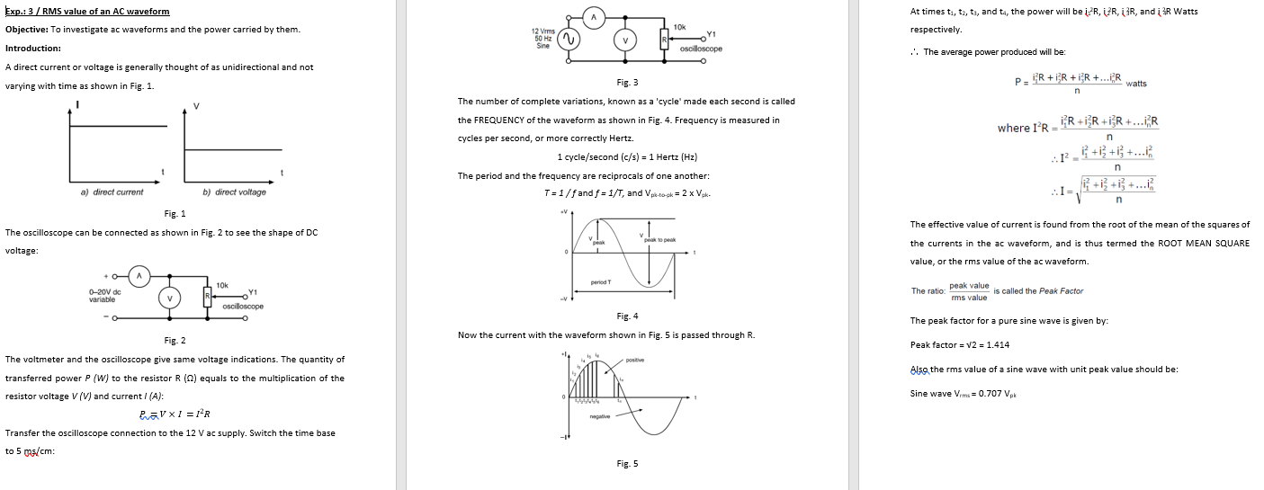
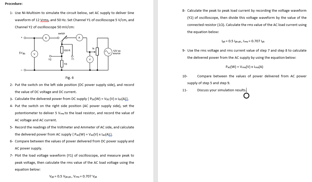
Exp.: 3 / RMS value of an AC waveform Objective: To investigate ac waveforms and the power carried by them. Introduction: At times ti, ta, ts, and ta, the power will be iz R, ZR,R, and i 3R Watts respectively. 12 Vrms 50 Hz Sine 10% Y1 oscilloscope . The average power produced will be: A direct current or voltage is generally thought of as unidirectional and not varying with time as shown in Fig. 1. PR+IR +iR +...ER watts n 1 V Fig: 3 The number of complete variations, known as a 'cycle' made each second is called the FREQUENCY of the waveform as shown in Fig. 4. Frequency is measured in cycles per second, or more correctly Hertz. 1 cycle/second (c/s) = 1 Hertz (Hz) The period and the frequency are reciprocals of one another: T=1/f and f = 1/T, and Vp-to-pk = 2 x Vek- n where IR - IR+iXR+iR +...R r - 4 +i +i +.. n a) direct current b) direct voltage ...I V n Fig. 1 The oscilloscope can be connected as shown in Fig. 2 to see the shape of DC voltage: The effective value of current is found from the root of the mean of the squares of the currents in the ac waveform, and is thus termed the ROOT MEAN SQUARE proper 0 value, or the rms value of the ac waveform. A periode 10k Y1 The ratio: 0-20V dc variable peak value is called the Peak Factor mms value oscilloscope Fig. 4 Now the current with the waveform shown in Fig. 5 is passed through R. The peak factor for a pure sine wave is given by: Peak factor = V2 = 1.414 positive Also the rms value of a sine wave with unit peak value should be: Fig. 2 The voltmeter and the oscilloscope give same voltage indications. The quantity of transferred power P (W) to the resistor R (2) equals to the multiplication of the resistor voltage V (V) and current I(A): RaVXI =R Sine Wave Vrms = 0.707 Vak negative Transfer the oscilloscope connection to the 12 V ac supply. Switch the time base to 5 mas/cm: Fig. 5 Procedure: 1- Use NI-Multisim to simulate the circuit below, set AC supply to deliver Sine waveform of 12 Vrms, and 50 Hz. Set Channel Y1 of oscilloscope 5 V/cm, and Channel Y2 of oscilloscope 50 mV/cm: 8- Calculate the peak to peak load current by recording the voltage waveform (Y2) of oscilloscope, then divide this voltage waveform by the value of the connected resistor (10). Calculate the rms value of the AC load current using the equation below: switch Ipk = 0.5 lpk-pk, Irms = 0.707 Ipk 100R 12V ac 9. Use the rms voltage and rms current value of step 7 and step 8 to calculate 5Vdc source the delivered power from the AC supply by using the equation below: 1R Pac(W) = Vrms(V) x Irms(A) Fig. 6 2- Put the switch on the left side position (DC power supply side), and record the value of DC voltage and DC current. 3- Calculate the delivered power from DC supply { Poc(W) = Voc(V) x loc(A)], 4- Put the switch on the right side position (AC power supply side), set the 10 Compare between the values of power delivered from AC power supply of step 5 and step 9. 11 Discuss your simulation results. potentiometer to deliver 5 Vrms to the load resistor, and record the value of AC voltage and AC current. 5- Record the readings of the Voltmeter and Ammeter of AC side, and calculate the delivered power from AC supply { Pac(W) = VAC(V) x lac(A) }, 6- Compare between the values of power delivered from DC power supply and AC power supply. 7- Plot the load voltage waveform (Y1) of oscilloscope, and measure peak to peak voltage, then calculate the rms value of the AC load voltage using the equation below: Vpk = 0.5 Vpk-pk, Vrms = 0.707 Vpk Exp.: 3 / RMS value of an AC waveform Objective: To investigate ac waveforms and the power carried by them. Introduction: At times ti, ta, ts, and ta, the power will be iz R, ZR,R, and i 3R Watts respectively. 12 Vrms 50 Hz Sine 10% Y1 oscilloscope . The average power produced will be: A direct current or voltage is generally thought of as unidirectional and not varying with time as shown in Fig. 1. PR+IR +iR +...ER watts n 1 V Fig: 3 The number of complete variations, known as a 'cycle' made each second is called the FREQUENCY of the waveform as shown in Fig. 4. Frequency is measured in cycles per second, or more correctly Hertz. 1 cycle/second (c/s) = 1 Hertz (Hz) The period and the frequency are reciprocals of one another: T=1/f and f = 1/T, and Vp-to-pk = 2 x Vek- n where IR - IR+iXR+iR +...R r - 4 +i +i +.. n a) direct current b) direct voltage ...I V n Fig. 1 The oscilloscope can be connected as shown in Fig. 2 to see the shape of DC voltage: The effective value of current is found from the root of the mean of the squares of the currents in the ac waveform, and is thus termed the ROOT MEAN SQUARE proper 0 value, or the rms value of the ac waveform. A periode 10k Y1 The ratio: 0-20V dc variable peak value is called the Peak Factor mms value oscilloscope Fig. 4 Now the current with the waveform shown in Fig. 5 is passed through R. The peak factor for a pure sine wave is given by: Peak factor = V2 = 1.414 positive Also the rms value of a sine wave with unit peak value should be: Fig. 2 The voltmeter and the oscilloscope give same voltage indications. The quantity of transferred power P (W) to the resistor R (2) equals to the multiplication of the resistor voltage V (V) and current I(A): RaVXI =R Sine Wave Vrms = 0.707 Vak negative Transfer the oscilloscope connection to the 12 V ac supply. Switch the time base to 5 mas/cm: Fig. 5 Procedure: 1- Use NI-Multisim to simulate the circuit below, set AC supply to deliver Sine waveform of 12 Vrms, and 50 Hz. Set Channel Y1 of oscilloscope 5 V/cm, and Channel Y2 of oscilloscope 50 mV/cm: 8- Calculate the peak to peak load current by recording the voltage waveform (Y2) of oscilloscope, then divide this voltage waveform by the value of the connected resistor (10). Calculate the rms value of the AC load current using the equation below: switch Ipk = 0.5 lpk-pk, Irms = 0.707 Ipk 100R 12V ac 9. Use the rms voltage and rms current value of step 7 and step 8 to calculate 5Vdc source the delivered power from the AC supply by using the equation below: 1R Pac(W) = Vrms(V) x Irms(A) Fig. 6 2- Put the switch on the left side position (DC power supply side), and record the value of DC voltage and DC current. 3- Calculate the delivered power from DC supply { Poc(W) = Voc(V) x loc(A)], 4- Put the switch on the right side position (AC power supply side), set the 10 Compare between the values of power delivered from AC power supply of step 5 and step 9. 11 Discuss your simulation results. potentiometer to deliver 5 Vrms to the load resistor, and record the value of AC voltage and AC current. 5- Record the readings of the Voltmeter and Ammeter of AC side, and calculate the delivered power from AC supply { Pac(W) = VAC(V) x lac(A) }, 6- Compare between the values of power delivered from DC power supply and AC power supply. 7- Plot the load voltage waveform (Y1) of oscilloscope, and measure peak to peak voltage, then calculate the rms value of the AC load voltage using the equation below: Vpk = 0.5 Vpk-pk, Vrms = 0.707 Vpk