

Question: Experiment 5: Centripetal Force and Uniform Circular Motion Introduction: This experiment examines properties of centripetal force and its relationship to uniform circular motion. In order
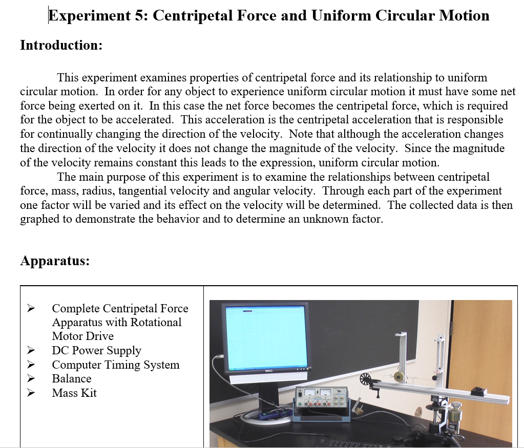
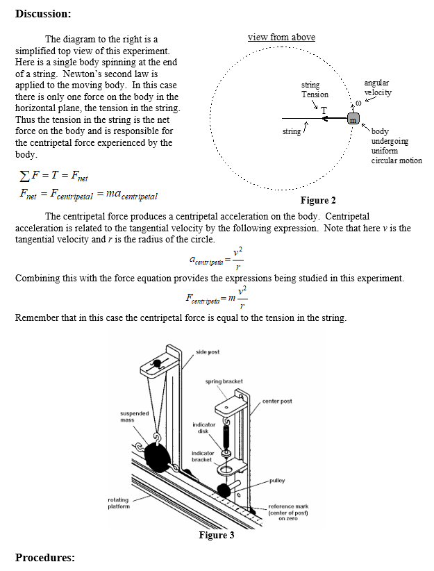
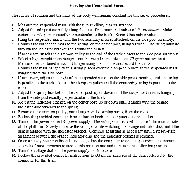
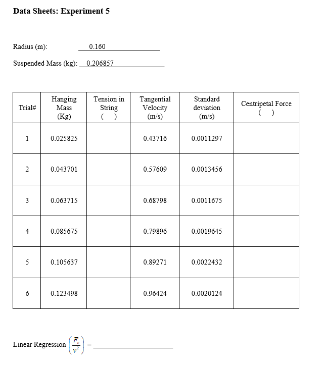
Experiment 5: Centripetal Force and Uniform Circular Motion Introduction: This experiment examines properties of centripetal force and its relationship to uniform circular motion. In order for any object to experience uniform circular motion it must have some net force being exerted on it. In this case the net force becomes the centripetal force, which is required for the object to be accelerated. This acceleration is the centripetal acceleration that is responsible for continually changing the direction of the velocity. Note that although the acceleration changes the direction of the velocity it does not change the magnitude of the velocity. Since the magnitude of the velocity remains constant this leads to the expression, uniform circular motion. The main purpose of this experiment is to examine the relationships between centripetal force, mass, radius, tangential velocity and angular velocity. Through each part of the experiment one factor will be varied and its effect on the velocity will be determined. The collected data is then graphed to demonstrate the behavior and to determine an unknown factor. Apparatus: Complete Centripetal Force Apparatus with Rotational Motor Drive DC Power Supply Computer Timing System Balance Mass Kit AAA Discussion: string The diagram to the right is a view from above simplified top view of this experiment. Here is a single body spinning at the end of a string. Newton's second law is applied to the moving body. In this case string angular there is only one force on the body in the Tension velocity horizontal plane, the tension in the string. Thus the tension in the string is the net force on the body and is responsible for body the centripetal force experienced by the undergoing uniform body. circular motion F=T = Fet Fnet = Fcentripetal = ma centripetal Figure 2 The centripetal force produces a centripetal acceleration on the body. Centripetal acceleration is related to the tangential velocity by the following expression. Note that here v is the tangential velocity and r is the radius of the circle. a centripetic 7' Combining this with the force equation provides the expressions being studied in this experiment. 12 Fcentripeta = 7 Remember that in this case the centripetal force is equal to the tension in the string. side post spring bracket center post suspended mass Indicator disk indicator bracket -pulley rotating platform reference mark (center of post) on zero Figure 3 Procedures: Varying the Centripetal Force The radius of rotation and the mass of the body will remain constant for this set of procedures. 1. Measure the suspended mass with the two auxiliary masses attached. 2. Adjust the side post assembly along the track for a rotational radius of 0.160 meters. Make certain the side post is exactly perpendicular to the track. Record this radius value. 3. Hang the suspended mass, with the two auxiliary masses attached, on the side post assembly. 4. Connect the suspended mass to the spring, on the center post, using a string. The string must go through the indicator bracket and around the pulley. 5. If necessary, attach the clamp-on pulley to the end of the track closest to the side post assembly. 6. Select a light weight mass hanger from the mass kit and place one 20 gram masses on it. Measure the combined mass and hanger using the balance and record the value. 7. Connect the mass hanger, with a string placed over the clamp-on pulley, to the suspended mass hanging from the side post. 8. If necessary, adjust the height of the suspended mass, on the side post assembly, until the string is parallel to the track. Adjust the clamp-on pulley until the connecting string is parallel to the track. 9. Adjust the spring bracket, on the center post, up or down until the suspended mass is hanging from the side post exactly perpendicular to the track. 10. Adjust the indicator bracket, on the center post, up or down until it aligns with the orange indicator disk attached to the spring. 11. Remove the clamp-on pulley, mass hanger and attaching string from the track. 12. Follow the provided computer instructions to begin the computer data collection. 13. Turn on the power to the DC power supply. The voltage dial is used to control the rotation rate of the platform. Slowly increase the voltage, while watching the orange indicator disk, until the disk is aligned with the indicator bracket. Continue adjusting as necessary until a steady-state alignment between the orange indicator disk and the indicator bracket is reached. 14. Once a steady-state condition is reached allow the computer to collect approximately twenty seconds of measurements related to this rotation rate and then stop the collection process. 15. Turn the voltage dial on the power supply, back to zero. 16. Follow the provided computer instructions to obtain the analyses of the data collected by the computer for this trial. Procedures (cont.): Repeatable Steps 1. Select a 20 gram mass from the mass kit and add it to the mass hanger together with the previous mass. Measure the total mass & hanger combination on the balance and record the value. 2. If necessary, attach the clamp-on pulley to the track and connect the mass hanger to the suspended mass with the string. 3. Adjust the spring bracket, on the center post up or down until the suspended mass is hanging from the side post exactly perpendicular to the track. 4. Adjust the indicator bracket, on the center post up or down until it aligns with the orange indicator disk. 5. Remove the clamp-on pulley, mass hanger and attaching string from the track. 6. Follow the provided computer instructions to begin the computer data collection. 7. Slowly increase the voltage, on the power supply, while watching the orange indicator disk. Adjust until the disk is aligned with the indicator bracket and a steady-state condition is reached. 8. Once a steady-state condition is reach, allow the computer to collect approximately twenty seconds of measurements related to this rotation rate and then stop the collection process. 9. Turn the voltage dial, on the power supply, back to zero. 10. Follow the provided computer instructions to obtain the analyses of the data collected by the computer for this trial. Conduct a total of 6 trials with each trial 20 grams greater than the previous. Data Analyses: The following calculations and subsequent graphs will help demonstrate and explain the relationships being studied in this experiment. 1. Calculate the tension in the string originally set-up for each trial (hanging mass), in newtons. 2. Calculate the centripetal force experienced by the suspended mass for each trial, in newtons. 3. Graph the tangential velocity as a function of centripetal force (using the hanging mass string tension) 4. Calculate the tangential velocity squared for each trial. 5. Graph tangential velocity squared and centripetal force (using the string tension). (v2 on the x-axes, Fc on the y-axes). This relationship is linear. Calculate the linear regression slope for this data. Use the slope to calculate the mass of the suspended body. Data Sheets: Experiment 5 Radius (m): 0.160 Suspended Mass (kg): 0.206857 Trial# Hanging Mass (Kg) Tension in String () Tangential Velocity (m/ Standard deviation (m/s) Centripetal Force 1 0.025825 0.43716 0.0011297 2 0.043701 0.57609 0.0013456 3 0.063715 0.68798 0.0011675 4 0.085675 0.79896 0.0019645 5 0.105637 0.89271 0.0022432 6 0.123498 0.96424 0.0020124 Linear Regression = Experiment 5: Centripetal Force and Uniform Circular Motion Introduction: This experiment examines properties of centripetal force and its relationship to uniform circular motion. In order for any object to experience uniform circular motion it must have some net force being exerted on it. In this case the net force becomes the centripetal force, which is required for the object to be accelerated. This acceleration is the centripetal acceleration that is responsible for continually changing the direction of the velocity. Note that although the acceleration changes the direction of the velocity it does not change the magnitude of the velocity. Since the magnitude of the velocity remains constant this leads to the expression, uniform circular motion. The main purpose of this experiment is to examine the relationships between centripetal force, mass, radius, tangential velocity and angular velocity. Through each part of the experiment one factor will be varied and its effect on the velocity will be determined. The collected data is then graphed to demonstrate the behavior and to determine an unknown factor. Apparatus: Complete Centripetal Force Apparatus with Rotational Motor Drive DC Power Supply Computer Timing System Balance Mass Kit AAA Discussion: string The diagram to the right is a view from above simplified top view of this experiment. Here is a single body spinning at the end of a string. Newton's second law is applied to the moving body. In this case string angular there is only one force on the body in the Tension velocity horizontal plane, the tension in the string. Thus the tension in the string is the net force on the body and is responsible for body the centripetal force experienced by the undergoing uniform body. circular motion F=T = Fet Fnet = Fcentripetal = ma centripetal Figure 2 The centripetal force produces a centripetal acceleration on the body. Centripetal acceleration is related to the tangential velocity by the following expression. Note that here v is the tangential velocity and r is the radius of the circle. a centripetic 7' Combining this with the force equation provides the expressions being studied in this experiment. 12 Fcentripeta = 7 Remember that in this case the centripetal force is equal to the tension in the string. side post spring bracket center post suspended mass Indicator disk indicator bracket -pulley rotating platform reference mark (center of post) on zero Figure 3 Procedures: Varying the Centripetal Force The radius of rotation and the mass of the body will remain constant for this set of procedures. 1. Measure the suspended mass with the two auxiliary masses attached. 2. Adjust the side post assembly along the track for a rotational radius of 0.160 meters. Make certain the side post is exactly perpendicular to the track. Record this radius value. 3. Hang the suspended mass, with the two auxiliary masses attached, on the side post assembly. 4. Connect the suspended mass to the spring, on the center post, using a string. The string must go through the indicator bracket and around the pulley. 5. If necessary, attach the clamp-on pulley to the end of the track closest to the side post assembly. 6. Select a light weight mass hanger from the mass kit and place one 20 gram masses on it. Measure the combined mass and hanger using the balance and record the value. 7. Connect the mass hanger, with a string placed over the clamp-on pulley, to the suspended mass hanging from the side post. 8. If necessary, adjust the height of the suspended mass, on the side post assembly, until the string is parallel to the track. Adjust the clamp-on pulley until the connecting string is parallel to the track. 9. Adjust the spring bracket, on the center post, up or down until the suspended mass is hanging from the side post exactly perpendicular to the track. 10. Adjust the indicator bracket, on the center post, up or down until it aligns with the orange indicator disk attached to the spring. 11. Remove the clamp-on pulley, mass hanger and attaching string from the track. 12. Follow the provided computer instructions to begin the computer data collection. 13. Turn on the power to the DC power supply. The voltage dial is used to control the rotation rate of the platform. Slowly increase the voltage, while watching the orange indicator disk, until the disk is aligned with the indicator bracket. Continue adjusting as necessary until a steady-state alignment between the orange indicator disk and the indicator bracket is reached. 14. Once a steady-state condition is reached allow the computer to collect approximately twenty seconds of measurements related to this rotation rate and then stop the collection process. 15. Turn the voltage dial on the power supply, back to zero. 16. Follow the provided computer instructions to obtain the analyses of the data collected by the computer for this trial. Procedures (cont.): Repeatable Steps 1. Select a 20 gram mass from the mass kit and add it to the mass hanger together with the previous mass. Measure the total mass & hanger combination on the balance and record the value. 2. If necessary, attach the clamp-on pulley to the track and connect the mass hanger to the suspended mass with the string. 3. Adjust the spring bracket, on the center post up or down until the suspended mass is hanging from the side post exactly perpendicular to the track. 4. Adjust the indicator bracket, on the center post up or down until it aligns with the orange indicator disk. 5. Remove the clamp-on pulley, mass hanger and attaching string from the track. 6. Follow the provided computer instructions to begin the computer data collection. 7. Slowly increase the voltage, on the power supply, while watching the orange indicator disk. Adjust until the disk is aligned with the indicator bracket and a steady-state condition is reached. 8. Once a steady-state condition is reach, allow the computer to collect approximately twenty seconds of measurements related to this rotation rate and then stop the collection process. 9. Turn the voltage dial, on the power supply, back to zero. 10. Follow the provided computer instructions to obtain the analyses of the data collected by the computer for this trial. Conduct a total of 6 trials with each trial 20 grams greater than the previous. Data Analyses: The following calculations and subsequent graphs will help demonstrate and explain the relationships being studied in this experiment. 1. Calculate the tension in the string originally set-up for each trial (hanging mass), in newtons. 2. Calculate the centripetal force experienced by the suspended mass for each trial, in newtons. 3. Graph the tangential velocity as a function of centripetal force (using the hanging mass string tension) 4. Calculate the tangential velocity squared for each trial. 5. Graph tangential velocity squared and centripetal force (using the string tension). (v2 on the x-axes, Fc on the y-axes). This relationship is linear. Calculate the linear regression slope for this data. Use the slope to calculate the mass of the suspended body. Data Sheets: Experiment 5 Radius (m): 0.160 Suspended Mass (kg): 0.206857 Trial# Hanging Mass (Kg) Tension in String () Tangential Velocity (m/ Standard deviation (m/s) Centripetal Force 1 0.025825 0.43716 0.0011297 2 0.043701 0.57609 0.0013456 3 0.063715 0.68798 0.0011675 4 0.085675 0.79896 0.0019645 5 0.105637 0.89271 0.0022432 6 0.123498 0.96424 0.0020124 Linear Regression =
Step by Step Solution
There are 3 Steps involved in it

Get step-by-step solutions from verified subject matter experts