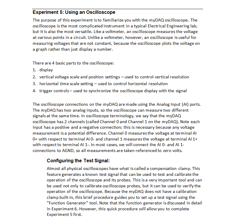
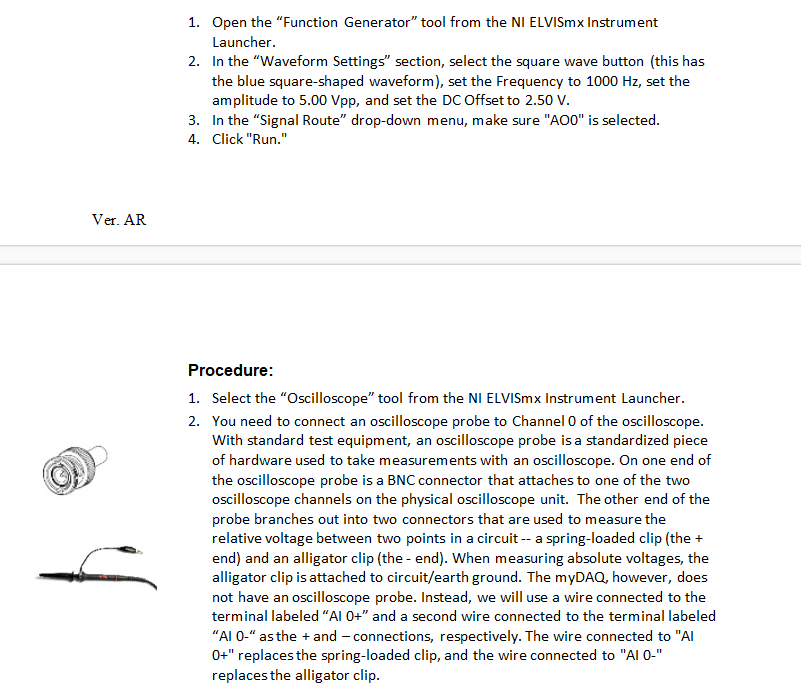
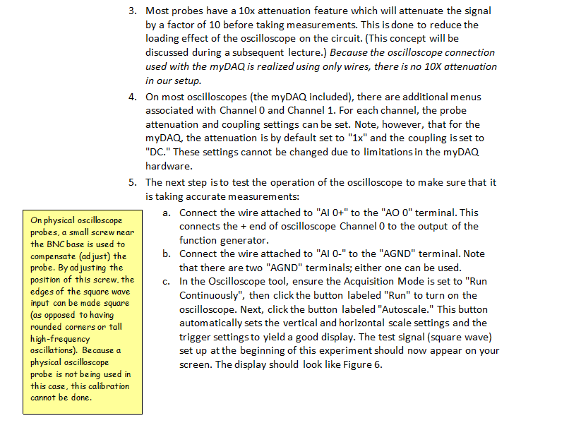
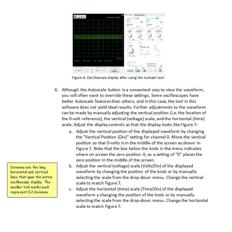
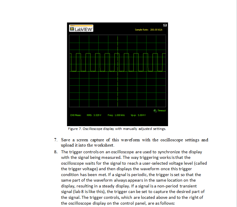
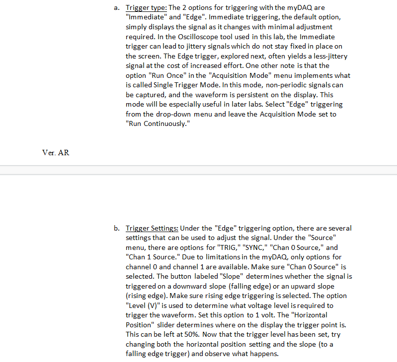
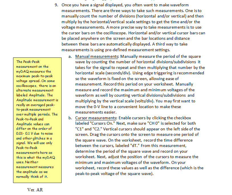
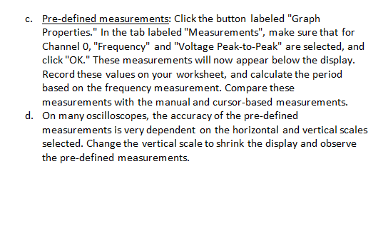
Experiment 5: Using an Oscilloscope The purpose of this experiment is to familiarize you with the myDAQ oscilloscope. The oscilloscope is the most complicated instrument in a typical Electrical Engineering lab, but it is also the most versatile. Like a voltmeter, an oscilloscope measures the voltage at various points in a circuit. Unlike a voltmeter, however, an oscilloscope is useful for measuring voltages that are not constant, because the oscilloscope plots the voltage on a graph rather than just display a number. There are 4 basic parts to the oscilloscope: 1. display 2. vertical voltage scale and position settings - used to control vertical resolution 3. horizontal time scale setting - used to control horizontal resolution 4. trigger controls used to synchronize the oscilloscope display with the signal The oscilloscope connections on the myDAQ are made using the Analog Input (AI) ports. The myDAQ has two analog inputs, so the oscilloscope can measure two different signals at the same time. In oscilloscope terminology, we say that the myDAQ oscilloscope has 2 channels (called Channel O and Channel 1 on the myDAQ). Note each input has a positive and a negative connection; this is necessary because any voltage measurement is a potential difference. Channel O measures the voltage at terminal Al O+ with respect to terminal AI O- and channel 1 measures the voltage at terminal Al 1+ with respect to terminal Al 1-. In most cases, we will connect the AI 0- and Al 1- connections to AGND, so all measurements are taken referenced to zero volts. Configuring the Test Signal: Almost all physical oscilloscopes have what is called a compensation clamp. This feature generates a known test signal that can be used to test and calibrate the operation of the oscilloscope and its probes. This is a very important tool and can be used not only to calibrate oscilloscope probes, but it can be used to verify the operation of the oscilloscope. Because the myDAQ does not have a calibration clamp built-in, this brief procedure guides you to set up a test signal using the "Function Generator" tool. Note that the function generator is discussed in detail in Experiment 6. However, this quick procedure will allow you to complete Experiment 5 first. 1. Open the "Function Generator" tool from the NI ELVISmx Instrument Launcher. 2. In the "Waveform Settings section, select the square wave button (this has the blue square-shaped waveform), set the Frequency to 1000 Hz, set the amplitude to 5.00 Vpp, and set the DC Offset to 2.50 V. 3. In the "Signal Route drop-down menu, make sure "A00" is selected. 4. Click "Run." Ver. AR Procedure: 1. Select the "Oscilloscope tool from the NI ELVISmx Instrument Launcher. 2. You need to connect an oscilloscope probe to Channel O of the oscilloscope. With standard test equipment, an oscilloscope probe is a standardized piece of hardware used to take measurements with an oscilloscope. On one end of the oscilloscope probe is a BNC connector that attaches to one of the two oscilloscope channels on the physical oscilloscope unit. The other end of the probe branches out into two connectors that are used to measure the relative voltage between two points in a circuit -- a spring-loaded clip (the + end) and an alligator clip (the-end). When measuring absolute voltages, the alligator clip is attached to circuit/earth ground. The myDAQ, however, does not have an oscilloscope probe. Instead, we will use a wire connected to the terminal labeled "Al O+" and a second wire connected to the terminal labeled AI 0-" as the + and connections, respectively. The wire connected to "AI 0+" replaces the spring-loaded clip, and the wire connected to "AIO-" replaces the alligator clip. 3. Most probes have a 10x attenuation feature which will attenuate the signal by a factor of 10 before taking measurements. This is done to reduce the loading effect of the oscilloscope on the circuit. (This concept will be discussed during a subsequent lecture.) Because the oscilloscope connection used with the myDAQ is realized using only wires, there is no 10X attenuation in our setup. 4. On most oscilloscopes (the myDAQ included), there are additional menus associated with Channel O and Channel 1. For each channel, the probe attenuation and coupling settings can be set. Note, however, that for the myDAQ, the attenuation is by default set to "1x" and the coupling is set to "DC." These settings cannot be changed due to limitations in the myDAQ hardware. 5. The next step is to test the operation of the oscilloscope to make sure that it is taking accurate measurements: a. Connect the wire attached to "Al 0+" to the "AO 0" terminal. This On physical oscilloscope probes, a small screw near connects the + end of oscilloscope Channel O to the output of the the BNC base is used to function generator. compensate (ad just) the b. Connect the wire attached to "AI 0-" to the "AGND" terminal. Note probe. By adjusting the that there are two "AGND" terminals; either one can be used. position of this screw, the C. In the Oscilloscope tool, ensure the Acquisition Mode is set to "Run edges of the square wave Continuously", then click the button labeled "Run" to turn on the input can be made square (as opposed to having oscilloscope. Next, click the button labeled "Autoscale." This button rounded corners or tall automatically sets the vertical and horizontal scale settings and the high-frequency trigger settings to yield a good display. The test signal (square wave) oscillations). Because a set up at the beginning of this experiment should now appear on your physical oscilloscope screen. The display should look like Figure 6. probe is not being used in this case, this calibration cannot be done. BEW . Figure 6. Oscilloscope display after using the Autoset tool. 6. Although the Autoscale button is a convenient way to view the waveform, you will often want to override these settings. Some oscilloscopes have better Autoscale features than others, and in this case, the tool in this software does not yield ideal results. Further adjustments to the waveform can be made by manually adjusting the vertical position (i.e. the location of the O-volt reference), the vertical (voltage) scale, and the horizontal (time) scale. Adjust the display controls so that the display looks like Figure 7: a. Adjust the vertical position of the displayed waveform by changing the "Vertical Position (Div)" setting for channel O. Move the vertical position so that O-volts is in the middle of the screen as shown in Figure 7. Note that the box below the knob in the menu indicates where on screen the zero position it, so a setting of "0" places the zero position in the middle of the screen. b. Adjust the vertical (voltage) scale (Volts/Div) of the displayed waveform by changing the position of the knob or by manually selecting the scale from the drop-down menu. Change the vertical scale to match Figure 7. c. Adjust the horizontal (time) scale (Time/Div) of the displayed waveform y changing the position of the knob or by manually selecting the scale from the drop-down menu. Change the horizontal scale to match Figure 7. Divisions are the long horizontal and vertical lines that span the entire oscilloscope display. The smaller tick marks each represent 0.2 divisions. LabVIEW Sample Rate: 200.00 ks/s Timeout CHO Meas: RMS: 3.529 V Freg: 1.000 6 Vpp: 5.004 V Figure 7. Oscilloscope display with manually adjusted settings. 7. Save a screen capture of this waveform with the oscilloscope settings and upload it into the worksheet. 8. The trigger controls on an oscilloscope are used to synchronize the display with the signal being measured. The way triggering works is that the oscilloscope waits for the signal to reach a user-selected voltage level (called the trigger voltage) and then displays the waveform once this trigger condition has been met. If a signal is periodic, the trigger is set so that the same part of the waveform always appears in the same location on the display, resulting in a steady display. If a signal is a non-period transient signal (lab 8 is like this), the trigger can be set to capture the desired part of the signal. The trigger controls, which are located above and to the right of the oscilloscope display on the control panel, are as follows: a. Trigger type: The 2 options for triggering with the myDAQ are "Immediate" and "Edge". Immediate triggering, the default option, simply displays the signal as it changes with minimal adjustment required. In the Oscilloscope tool used in this lab, the Immediate trigger can lead to jittery signals which do not stay fixed in place on the screen. The Edge trigger, explored next, often yields a less-jittery signal at the cost of increased effort. One other note is that the option "Run Once" in the "Acquisition Mode" menu implements what is called Single Trigger Mode. In this mode, non-periodic signals can be captured, and the waveform is persistent on the display. This mode will be especially useful in later labs. Select "Edge" triggering from the drop-down menu and leave the Acquisition Mode set to "Run Continuously." Ver. AR b. Trigger Settings: Under the "Edge" triggering option, there are several settings that can be used to adjust the signal. Under the "Source" menu, there are options for "TRIG," "SYNC," "Chan Source," and "Chan 1 Source." Due to limitations in the myDAQ, only options for channel and channel 1 are available. Make sure "Chan 0 Source" is selected. The button labeled "Slope" determines whether the signal is triggered on a downward slope (falling edge) or an upward slope (rising edge). Make sure rising edge triggering is selected. The option "Level (V)" is used to determine what voltage level is required to trigger the waveform. Set this option to 1 volt. The "Horizontal Position" slider determines where on the display the trigger point is. This can be left at 50%. Now that the trigger level has been set, try changing both the horizontal position setting and the slope (to a falling edge trigger) and observe what happens. 9. Once you have a signal displayed, you often want to make waveform measurements. There are three ways to take such measurements. One is to manually count the number of divisions (horizontal and/or vertical) and then multiply by the horizontal/vertical scale settings to get the time and/or the voltage measurements. A more precise way to take measurements is to use the cursor bars on the oscilloscope. Horizontal and/or vertical cursor bars can be placed anywhere on the screen and the bar locations and distance between these bars are automatically displayed. A third way to take measurements is using pre-defined measurement settings. a. Manual measurements: Manually measure the period of the square The Peak Peak wave by counting the number of horizontal divisions/subdivisions it measurement on the takes for the signal to repeat and then multiplying that number by the myDAQ measures the horizontal scale (seconds/div). Using edge triggering is recommended maximum peak-to-peak voltage spread. On some so the waveform is fixed on the screen, allowing ease of oscilloscopes, there is an measurement. Record this period on your worksheet. Manually alternate measurement measure and record the maximum and minimum voltages of the labe led Amplitude. The waveform as well by counting vertical divisions/subdivisions and Amplitude measurement is multiplying by the vertical scale (volts/div). You may first want to really an averaged peak- to-peak measurement move the O-V line to a convenient location to make these over multiple periods. The measurements easier. Peak-to-Peak and b. Cursor measurements: Enable cursors by clicking the checkbox Amplitude values can labeled "Cursors On." Next, make sure "CH 0" is selected for both differ on the order of "C1" and "C2." Vertical cursors should appear on the left side of the 0.01- 0.1 V due to noise screen. Drag the cursors onto the screen to measure one period of and other glitches in a signal. We will use only the square wave. On the worksheet, record the time difference between the cursors, labeled "dT." From this measurement, Peak-to-Peak measurements here as determine the period of the square wave and record on your this is what the myDAQ worksheet. Next, adjust the position of the cursors to measure the uses. Neither minimum and maximum voltages of the waveform. On your measurement measures worksheet, record these values as well as the difference (which is the the amplitude as we peak-to-peak voltage of the square wave). normally think of it. Ver. AR c. Pre-defined measurements: Click the button labeled "Graph Properties." In the tab labeled "Measurements", make sure that for Channel 0, "Frequency" and "Voltage Peak-to-Peak" are selected, and click "OK." These measurements will now appear below the display. Record these values on your worksheet, and calculate the period based on the frequency measurement. Compare these measurements with the manual and cursor-based measurements. d. On many oscilloscopes, the accuracy of the pre-defined measurements is very dependent on the horizontal and vertical scales selected. Change the vertical scale to shrink the display and observe the pre-defined measurements. Experiment 6: Using a Function Generator The purpose of this experiment is to familiarize you with the myDAQ function generator and to continue practice using the oscilloscope. A function generator is used to generate non-constant test signals to drive circuits. Most function generators can create sinusoids, square waves, and triangle waves. Some function generators (but not this one) can also create saw-tooth waveforms. Standard function generators use BNC connectors, similar to those used for oscilloscopes, to connect the function generator to the circuit. Because the myDAQ does not have these connectors, simple wire connections to terminals "AO 0," "AO1," and "AGND" are used. Procedure: 1. Make sure the oscilloscope and function generator are connected as in Experiment 5. Make sure the Oscilloscope tool and the Function Generator tool are both open. 2. Set up the function generator to supply a sinusoid with a frequency of 100 Hz, amplitude of 6 Vpp, and dc offset of Ov: a. Select the button labeled with the image of a green sinusoid. b. Set the frequency of the signal to 100 Hz. C. Set the amplitude of the signal to 6 Vpp. d. Set the dc offset of the signal to 0 V. 3. Turn on the function generator by selecting the button labeled "Run." 4. Observe the output of the function generator on Channel o of the oscilloscope. Click the Autoscale button or manually set the vertical and horizontal scales to get a good display. 5. Set the oscilloscope to measure and display the frequency, amplitude, maximum and minimum values. Note that the maximum and minimum values are found using the cursors, not via the pre-defined measurements. Calculate the mean of the signal from the maximum and minimum values, record these values on your worksheet, and comment on how steady the values appear to be. Refer to Experiment 5 for instructions on displaying oscilloscope measurements. 6. Save a screen capture of the oscilloscope display and upload it into the worksheet. 7. Without changing the signal, change the vertical and horizontal scales (both directions) and observe how the displayed measurements change. Q4 (answer on your lab worksheet): For sinusoidal signals, explain the difference between the way we normally define "Amplitude" and the "Amplitude" setting in the myDAQ Function Generator. Ver. AR 05 (answer on your lab worksheet): What happens to the amplitude measurement if the vertical scale is set too high? What happens to it if the vertical scale is set too low? What about the horizontal scales and the frequency measurement? Also, discuss briefly how you would choose a proper vertical scale for a waveform of known amplitude V to get the most accurate measurements. Q6 (answer on your lab worksheet): Based on your observations in Experiment 6, derive an expression for an appropriate oscilloscope time scale (horizontal scale) for a waveform of frequency 'P (in Hz), so that only two complete waveforms are seen on the oscilloscope screen. Hint: The period (T) of a waveform is the time required to complete one cycle and is the inverse of frequency (f). 8. Change the output of the function generator by adding a dc offset of 3.0 V and repeat steps 4-5. Adjust the oscilloscope settings as needed to get a good display. On your worksheet, indicate which of these measurements changed from step 5. 9. Take a screen capture of the oscilloscope display and upload it into the worksheet. 10. Experiment with different waveform shapes (square wave, triangle wave), amplitude, frequency, and dc offset settings on the function generating, making sure to get a good display on the oscilloscope each time you change a setting. Also, experiment with changing the horizontal and vertical scales on the oscilloscope and noting how these changes affect (or don't affect) the measurements. 11. Set the function generator to be an 10 Vpp sinusoid with 1000 Hz frequency and DC offset of 2.5 V. Use this signal as the input to your circuit from Experiment 4 (Figure 4), replacing the DC voltage source. Connect oscilloscope Channel O (AI O+ and AI 0-) to measure the input signal. Connect Channel 1 (Al 1+ and Al 1-) to measure the voltage across resistor Rs. Adjust the oscilloscope settings as needed to get a good display showing both the input and output signals superimposed on each other. Make sure that the vertical scales are the same so that you can visually see the difference in voltage between the input and output signals. 12. Save a screen capture of the oscilloscope display and upload it into the worksheet. Experiment 5: Using an Oscilloscope The purpose of this experiment is to familiarize you with the myDAQ oscilloscope. The oscilloscope is the most complicated instrument in a typical Electrical Engineering lab, but it is also the most versatile. Like a voltmeter, an oscilloscope measures the voltage at various points in a circuit. Unlike a voltmeter, however, an oscilloscope is useful for measuring voltages that are not constant, because the oscilloscope plots the voltage on a graph rather than just display a number. There are 4 basic parts to the oscilloscope: 1. display 2. vertical voltage scale and position settings - used to control vertical resolution 3. horizontal time scale setting - used to control horizontal resolution 4. trigger controls used to synchronize the oscilloscope display with the signal The oscilloscope connections on the myDAQ are made using the Analog Input (AI) ports. The myDAQ has two analog inputs, so the oscilloscope can measure two different signals at the same time. In oscilloscope terminology, we say that the myDAQ oscilloscope has 2 channels (called Channel O and Channel 1 on the myDAQ). Note each input has a positive and a negative connection; this is necessary because any voltage measurement is a potential difference. Channel O measures the voltage at terminal Al O+ with respect to terminal AI O- and channel 1 measures the voltage at terminal Al 1+ with respect to terminal Al 1-. In most cases, we will connect the AI 0- and Al 1- connections to AGND, so all measurements are taken referenced to zero volts. Configuring the Test Signal: Almost all physical oscilloscopes have what is called a compensation clamp. This feature generates a known test signal that can be used to test and calibrate the operation of the oscilloscope and its probes. This is a very important tool and can be used not only to calibrate oscilloscope probes, but it can be used to verify the operation of the oscilloscope. Because the myDAQ does not have a calibration clamp built-in, this brief procedure guides you to set up a test signal using the "Function Generator" tool. Note that the function generator is discussed in detail in Experiment 6. However, this quick procedure will allow you to complete Experiment 5 first. 1. Open the "Function Generator" tool from the NI ELVISmx Instrument Launcher. 2. In the "Waveform Settings section, select the square wave button (this has the blue square-shaped waveform), set the Frequency to 1000 Hz, set the amplitude to 5.00 Vpp, and set the DC Offset to 2.50 V. 3. In the "Signal Route drop-down menu, make sure "A00" is selected. 4. Click "Run." Ver. AR Procedure: 1. Select the "Oscilloscope tool from the NI ELVISmx Instrument Launcher. 2. You need to connect an oscilloscope probe to Channel O of the oscilloscope. With standard test equipment, an oscilloscope probe is a standardized piece of hardware used to take measurements with an oscilloscope. On one end of the oscilloscope probe is a BNC connector that attaches to one of the two oscilloscope channels on the physical oscilloscope unit. The other end of the probe branches out into two connectors that are used to measure the relative voltage between two points in a circuit -- a spring-loaded clip (the + end) and an alligator clip (the-end). When measuring absolute voltages, the alligator clip is attached to circuit/earth ground. The myDAQ, however, does not have an oscilloscope probe. Instead, we will use a wire connected to the terminal labeled "Al O+" and a second wire connected to the terminal labeled AI 0-" as the + and connections, respectively. The wire connected to "AI 0+" replaces the spring-loaded clip, and the wire connected to "AIO-" replaces the alligator clip. 3. Most probes have a 10x attenuation feature which will attenuate the signal by a factor of 10 before taking measurements. This is done to reduce the loading effect of the oscilloscope on the circuit. (This concept will be discussed during a subsequent lecture.) Because the oscilloscope connection used with the myDAQ is realized using only wires, there is no 10X attenuation in our setup. 4. On most oscilloscopes (the myDAQ included), there are additional menus associated with Channel O and Channel 1. For each channel, the probe attenuation and coupling settings can be set. Note, however, that for the myDAQ, the attenuation is by default set to "1x" and the coupling is set to "DC." These settings cannot be changed due to limitations in the myDAQ hardware. 5. The next step is to test the operation of the oscilloscope to make sure that it is taking accurate measurements: a. Connect the wire attached to "Al 0+" to the "AO 0" terminal. This On physical oscilloscope probes, a small screw near connects the + end of oscilloscope Channel O to the output of the the BNC base is used to function generator. compensate (ad just) the b. Connect the wire attached to "AI 0-" to the "AGND" terminal. Note probe. By adjusting the that there are two "AGND" terminals; either one can be used. position of this screw, the C. In the Oscilloscope tool, ensure the Acquisition Mode is set to "Run edges of the square wave Continuously", then click the button labeled "Run" to turn on the input can be made square (as opposed to having oscilloscope. Next, click the button labeled "Autoscale." This button rounded corners or tall automatically sets the vertical and horizontal scale settings and the high-frequency trigger settings to yield a good display. The test signal (square wave) oscillations). Because a set up at the beginning of this experiment should now appear on your physical oscilloscope screen. The display should look like Figure 6. probe is not being used in this case, this calibration cannot be done. BEW . Figure 6. Oscilloscope display after using the Autoset tool. 6. Although the Autoscale button is a convenient way to view the waveform, you will often want to override these settings. Some oscilloscopes have better Autoscale features than others, and in this case, the tool in this software does not yield ideal results. Further adjustments to the waveform can be made by manually adjusting the vertical position (i.e. the location of the O-volt reference), the vertical (voltage) scale, and the horizontal (time) scale. Adjust the display controls so that the display looks like Figure 7: a. Adjust the vertical position of the displayed waveform by changing the "Vertical Position (Div)" setting for channel O. Move the vertical position so that O-volts is in the middle of the screen as shown in Figure 7. Note that the box below the knob in the menu indicates where on screen the zero position it, so a setting of "0" places the zero position in the middle of the screen. b. Adjust the vertical (voltage) scale (Volts/Div) of the displayed waveform by changing the position of the knob or by manually selecting the scale from the drop-down menu. Change the vertical scale to match Figure 7. c. Adjust the horizontal (time) scale (Time/Div) of the displayed waveform y changing the position of the knob or by manually selecting the scale from the drop-down menu. Change the horizontal scale to match Figure 7. Divisions are the long horizontal and vertical lines that span the entire oscilloscope display. The smaller tick marks each represent 0.2 divisions. LabVIEW Sample Rate: 200.00 ks/s Timeout CHO Meas: RMS: 3.529 V Freg: 1.000 6 Vpp: 5.004 V Figure 7. Oscilloscope display with manually adjusted settings. 7. Save a screen capture of this waveform with the oscilloscope settings and upload it into the worksheet. 8. The trigger controls on an oscilloscope are used to synchronize the display with the signal being measured. The way triggering works is that the oscilloscope waits for the signal to reach a user-selected voltage level (called the trigger voltage) and then displays the waveform once this trigger condition has been met. If a signal is periodic, the trigger is set so that the same part of the waveform always appears in the same location on the display, resulting in a steady display. If a signal is a non-period transient signal (lab 8 is like this), the trigger can be set to capture the desired part of the signal. The trigger controls, which are located above and to the right of the oscilloscope display on the control panel, are as follows: a. Trigger type: The 2 options for triggering with the myDAQ are "Immediate" and "Edge". Immediate triggering, the default option, simply displays the signal as it changes with minimal adjustment required. In the Oscilloscope tool used in this lab, the Immediate trigger can lead to jittery signals which do not stay fixed in place on the screen. The Edge trigger, explored next, often yields a less-jittery signal at the cost of increased effort. One other note is that the option "Run Once" in the "Acquisition Mode" menu implements what is called Single Trigger Mode. In this mode, non-periodic signals can be captured, and the waveform is persistent on the display. This mode will be especially useful in later labs. Select "Edge" triggering from the drop-down menu and leave the Acquisition Mode set to "Run Continuously." Ver. AR b. Trigger Settings: Under the "Edge" triggering option, there are several settings that can be used to adjust the signal. Under the "Source" menu, there are options for "TRIG," "SYNC," "Chan Source," and "Chan 1 Source." Due to limitations in the myDAQ, only options for channel and channel 1 are available. Make sure "Chan 0 Source" is selected. The button labeled "Slope" determines whether the signal is triggered on a downward slope (falling edge) or an upward slope (rising edge). Make sure rising edge triggering is selected. The option "Level (V)" is used to determine what voltage level is required to trigger the waveform. Set this option to 1 volt. The "Horizontal Position" slider determines where on the display the trigger point is. This can be left at 50%. Now that the trigger level has been set, try changing both the horizontal position setting and the slope (to a falling edge trigger) and observe what happens. 9. Once you have a signal displayed, you often want to make waveform measurements. There are three ways to take such measurements. One is to manually count the number of divisions (horizontal and/or vertical) and then multiply by the horizontal/vertical scale settings to get the time and/or the voltage measurements. A more precise way to take measurements is to use the cursor bars on the oscilloscope. Horizontal and/or vertical cursor bars can be placed anywhere on the screen and the bar locations and distance between these bars are automatically displayed. A third way to take measurements is using pre-defined measurement settings. a. Manual measurements: Manually measure the period of the square The Peak Peak wave by counting the number of horizontal divisions/subdivisions it measurement on the takes for the signal to repeat and then multiplying that number by the myDAQ measures the horizontal scale (seconds/div). Using edge triggering is recommended maximum peak-to-peak voltage spread. On some so the waveform is fixed on the screen, allowing ease of oscilloscopes, there is an measurement. Record this period on your worksheet. Manually alternate measurement measure and record the maximum and minimum voltages of the labe led Amplitude. The waveform as well by counting vertical divisions/subdivisions and Amplitude measurement is multiplying by the vertical scale (volts/div). You may first want to really an averaged peak- to-peak measurement move the O-V line to a convenient location to make these over multiple periods. The measurements easier. Peak-to-Peak and b. Cursor measurements: Enable cursors by clicking the checkbox Amplitude values can labeled "Cursors On." Next, make sure "CH 0" is selected for both differ on the order of "C1" and "C2." Vertical cursors should appear on the left side of the 0.01- 0.1 V due to noise screen. Drag the cursors onto the screen to measure one period of and other glitches in a signal. We will use only the square wave. On the worksheet, record the time difference between the cursors, labeled "dT." From this measurement, Peak-to-Peak measurements here as determine the period of the square wave and record on your this is what the myDAQ worksheet. Next, adjust the position of the cursors to measure the uses. Neither minimum and maximum voltages of the waveform. On your measurement measures worksheet, record these values as well as the difference (which is the the amplitude as we peak-to-peak voltage of the square wave). normally think of it. Ver. AR c. Pre-defined measurements: Click the button labeled "Graph Properties." In the tab labeled "Measurements", make sure that for Channel 0, "Frequency" and "Voltage Peak-to-Peak" are selected, and click "OK." These measurements will now appear below the display. Record these values on your worksheet, and calculate the period based on the frequency measurement. Compare these measurements with the manual and cursor-based measurements. d. On many oscilloscopes, the accuracy of the pre-defined measurements is very dependent on the horizontal and vertical scales selected. Change the vertical scale to shrink the display and observe the pre-defined measurements. Experiment 6: Using a Function Generator The purpose of this experiment is to familiarize you with the myDAQ function generator and to continue practice using the oscilloscope. A function generator is used to generate non-constant test signals to drive circuits. Most function generators can create sinusoids, square waves, and triangle waves. Some function generators (but not this one) can also create saw-tooth waveforms. Standard function generators use BNC connectors, similar to those used for oscilloscopes, to connect the function generator to the circuit. Because the myDAQ does not have these connectors, simple wire connections to terminals "AO 0," "AO1," and "AGND" are used. Procedure: 1. Make sure the oscilloscope and function generator are connected as in Experiment 5. Make sure the Oscilloscope tool and the Function Generator tool are both open. 2. Set up the function generator to supply a sinusoid with a frequency of 100 Hz, amplitude of 6 Vpp, and dc offset of Ov: a. Select the button labeled with the image of a green sinusoid. b. Set the frequency of the signal to 100 Hz. C. Set the amplitude of the signal to 6 Vpp. d. Set the dc offset of the signal to 0 V. 3. Turn on the function generator by selecting the button labeled "Run." 4. Observe the output of the function generator on Channel o of the oscilloscope. Click the Autoscale button or manually set the vertical and horizontal scales to get a good display. 5. Set the oscilloscope to measure and display the frequency, amplitude, maximum and minimum values. Note that the maximum and minimum values are found using the cursors, not via the pre-defined measurements. Calculate the mean of the signal from the maximum and minimum values, record these values on your worksheet, and comment on how steady the values appear to be. Refer to Experiment 5 for instructions on displaying oscilloscope measurements. 6. Save a screen capture of the oscilloscope display and upload it into the worksheet. 7. Without changing the signal, change the vertical and horizontal scales (both directions) and observe how the displayed measurements change. Q4 (answer on your lab worksheet): For sinusoidal signals, explain the difference between the way we normally define "Amplitude" and the "Amplitude" setting in the myDAQ Function Generator. Ver. AR 05 (answer on your lab worksheet): What happens to the amplitude measurement if the vertical scale is set too high? What happens to it if the vertical scale is set too low? What about the horizontal scales and the frequency measurement? Also, discuss briefly how you would choose a proper vertical scale for a waveform of known amplitude V to get the most accurate measurements. Q6 (answer on your lab worksheet): Based on your observations in Experiment 6, derive an expression for an appropriate oscilloscope time scale (horizontal scale) for a waveform of frequency 'P (in Hz), so that only two complete waveforms are seen on the oscilloscope screen. Hint: The period (T) of a waveform is the time required to complete one cycle and is the inverse of frequency (f). 8. Change the output of the function generator by adding a dc offset of 3.0 V and repeat steps 4-5. Adjust the oscilloscope settings as needed to get a good display. On your worksheet, indicate which of these measurements changed from step 5. 9. Take a screen capture of the oscilloscope display and upload it into the worksheet. 10. Experiment with different waveform shapes (square wave, triangle wave), amplitude, frequency, and dc offset settings on the function generating, making sure to get a good display on the oscilloscope each time you change a setting. Also, experiment with changing the horizontal and vertical scales on the oscilloscope and noting how these changes affect (or don't affect) the measurements. 11. Set the function generator to be an 10 Vpp sinusoid with 1000 Hz frequency and DC offset of 2.5 V. Use this signal as the input to your circuit from Experiment 4 (Figure 4), replacing the DC voltage source. Connect oscilloscope Channel O (AI O+ and AI 0-) to measure the input signal. Connect Channel 1 (Al 1+ and Al 1-) to measure the voltage across resistor Rs. Adjust the oscilloscope settings as needed to get a good display showing both the input and output signals superimposed on each other. Make sure that the vertical scales are the same so that you can visually see the difference in voltage between the input and output signals. 12. Save a screen capture of the oscilloscope display and upload it into the worksheet


