Answered step by step
Verified Expert Solution
Question
1 Approved Answer
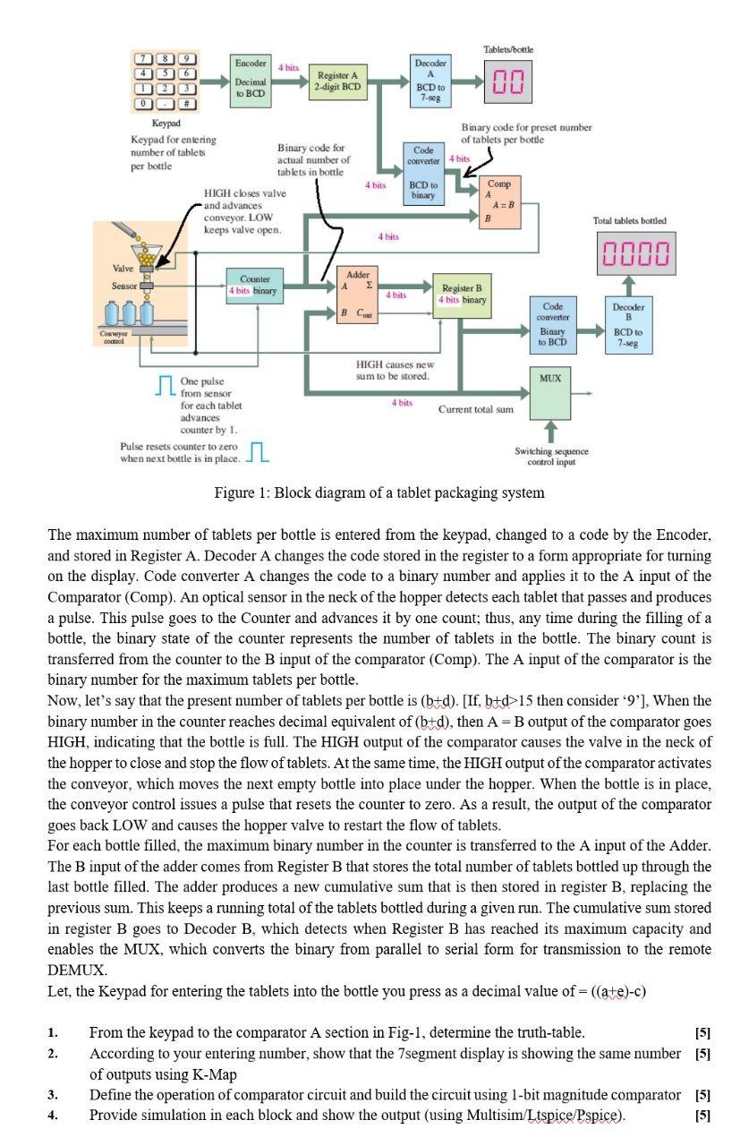
Figure 1: Block diagram of a tablet packaging system The maximum number of tablets per bottle is entered from the keypad, changed to a code

Figure 1: Block diagram of a tablet packaging system The maximum number of tablets per bottle is entered from the keypad, changed to a code by the Encoder, and stored in Register A. Decoder A changes the code stored in the register to a form appropriate for turning on the display. Code converter A changes the code to a binary number and applies it to the A input of the Comparator (Comp). An optical sensor in the neck of the hopper detects each tablet that passes and produces a pulse. This pulse goes to the Counter and advances it by one count; thus, any time during the filling of a bottle, the binary state of the counter represents the number of tablets in the bottle. The binary count is transferred from the counter to the B input of the comparator (Comp). The A input of the comparator is the binary number for the maximum tablets per bottle. Now, let's say that the present number of tablets per bottle is ( b+d ). [If, b+d>15 then consider ' 9 '], When the binary number in the counter reaches decimal equivalent of (b+d), then A=B output of the comparator goes HIGH, indicating that the bottle is full. The HIGH output of the comparator causes the valve in the neck of the hopper to close and stop the flow of tablets. At the same time, the HIGH output of the comparator activates the conveyor, which moves the next empty bottle into place under the hopper. When the bottle is in place, the conveyor control issues a pulse that resets the counter to zero. As a result, the output of the comparator goes back LOW and causes the hopper valve to restart the flow of tablets. For each bottle filled, the maximum binary number in the counter is transferred to the A input of the Adder. The B input of the adder comes from Register B that stores the total number of tablets bottled up through the last bottle filled. The adder produces a new cumulative sum that is then stored in register B, replacing the previous sum. This keeps a running total of the tablets bottled during a given run. The cumulative sum stored in register B goes to Decoder B, which detects when Register B has reached its maximum capacity and enables the MUX, which converts the binary from parallel to serial form for transmission to the remote DEMUX. Let, the Keypad for entering the tablets into the bottle you press as a decimal value of =((a+e)c) 1. From the keypad to the comparator A section in Fig-1, determine the truth-table. [2] 2. According to your entering number, show that the 7segment display is showing the same number [5] of outputs using K-Map 3. Define the operation of comparator circuit and build the circuit using 1-bit magnitude comparator [5] 4. Provide simulation in each block and show the output (using Multisim/Ltspice/Pspice). [5]
Step by Step Solution
There are 3 Steps involved in it
Step: 1

Get Instant Access to Expert-Tailored Solutions
See step-by-step solutions with expert insights and AI powered tools for academic success
Step: 2

Step: 3

Ace Your Homework with AI
Get the answers you need in no time with our AI-driven, step-by-step assistance
Get Started


