

Question: ?? Problems (4) to (8) below are based on Example Problem 13.4 Example Problem 13.4 FIGURE 13.41 System for Example Problem 13.4 80 ft Figure

??
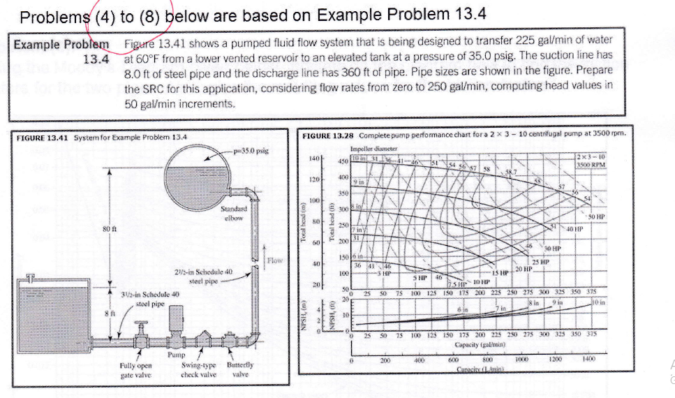
Problems (4) to (8) below are based on Example Problem 13.4 Example Problem 13.4 FIGURE 13.41 System for Example Problem 13.4 80 ft Figure 13.41 shows a pumped fluid flow system that is being designed to transfer 225 gal/min of water at 60F from a lower vented reservoir to an elevated tank at a pressure of 35.0 psig. The suction line has 8.0 ft of steel pipe and the discharge line has 360 ft of pipe. Pipe sizes are shown in the figure. Prepare the SRC for this application, considering flow rates from zero to 250 gal/min, computing head values in 50 gal/min increments. 811 31/2-in Schedule 40 steel pipe Fully open gate valve 21/2-in Schedule 40 steel pipe - Pump -p35.0 psig Swing-type check valve Standard elbow Butterfly valve Flow FIGURE 13.28 Complete pump performance chart for a 2 x 3-10 centrifugal pump at 3500 rpm. Impeller diameter 450031364146515446\ 10 in 31. 140 120 100 80 60 40 20 Total head (ft) NPSH, (0 400 350 300 250 100 7 in 31 200 1506 in in 50 19 in 0 20 10 in 0 6 36 41 46 3 HP 25 50 25 75 200 SHP 100 125 400 46 6 in 57 58 600 58. 800 Capacity (LAnin Xx 2 46 20 HP KR 31 1000 52 30 HP 25 HP 15 HP SHP 10 HP 150 175 200 225 250 275 300 325 350 375 8 in 9 in 10 in 7 in 50 75 100 125 150 175 200 225 250 275 300 325 350 375 Capacity (gal/min) 2x3-10 3500 RPM 56 1200 40 HP 50 HP 1400 roblem (5): Using the pipe sizes from Problem (4), what are the inside diameters and areas of the two pipes? Calculate D/E and NR for each pipe.
Step by Step Solution
3.36 Rating (149 Votes )
There are 3 Steps involved in it
To answer Problem 5 lets determine the inside diameters and areas of the two pipes and calculate D and N Reynolds number for each Step 1 Identifying t... View full answer

Get step-by-step solutions from verified subject matter experts