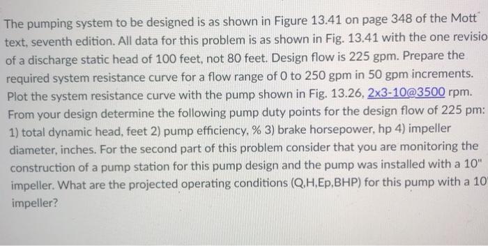
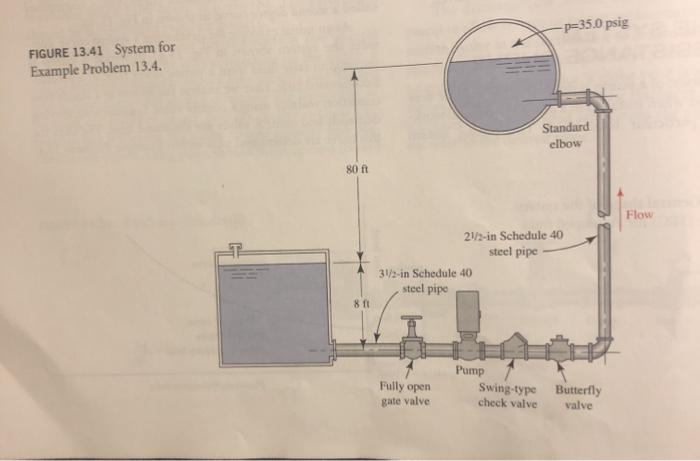
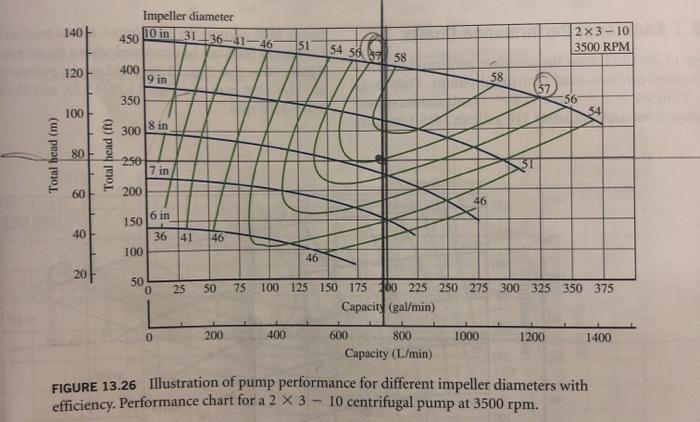
The pumping system to be designed is as shown in Figure 13.41 on page 348 of the Mott text, seventh edition. All data for this problem is as shown in Fig. 13.41 with the one revisio of a discharge static head of 100 feet, not 80 feet. Design flow is 225 gpm. Prepare the required system resistance curve for a flow range of 0 to 250 gpm in 50 gpm increments. Plot the system resistance curve with the pump shown in Fig. 13.26, 2x3-10@3500 rpm. From your design determine the following pump duty points for the design flow of 225 pm: 1) total dynamic head, feet 2) pump efficiency. % 3) brake horsepower, hp 4) impeller diameter, inches. For the second part of this problem consider that you are monitoring the construction of a pump station for this pump design and the pump was installed with a 10" impeller. What are the projected operating conditions (Q.H.Ep,BHP) for this pump with a 10 impeller? -p=35.0 psig FIGURE 13.41 System for Example Problem 13.4. Standard elbow 80 ft Flow 21/3-in Schedule 40 steel pipe 31/2-in Schedule 40 steel pipe 811 Pump Fully open Swing-type Butterfly check valve valve gate valve 140 Impeller diameter 450 10 in 31_36-41-46 2 x 3-10 3500 RPM 151 54 56 37 58 120 400 9 in 58 350 56 100 300 8 in Total head (m) 80 Total head (ft) 250 7 in 200 60 46 6 in 150 40 36 41 46 100 46 20 SO 0 25 50 75 100 125 150 175 180 225 250 275 300 325 350 375 Capacity (gal/min) 0 200 400 1000 1200 1400 600 800 Capacity (L/min) FIGURE 13.26 Illustration of pump performance for different impeller diameters with efficiency. Performance chart for a 2 X 3 - 10 centrifugal pump at 3500 rpm. The pumping system to be designed is as shown in Figure 13.41 on page 348 of the Mott text, seventh edition. All data for this problem is as shown in Fig. 13.41 with the one revisio of a discharge static head of 100 feet, not 80 feet. Design flow is 225 gpm. Prepare the required system resistance curve for a flow range of 0 to 250 gpm in 50 gpm increments. Plot the system resistance curve with the pump shown in Fig. 13.26, 2x3-10@3500 rpm. From your design determine the following pump duty points for the design flow of 225 pm: 1) total dynamic head, feet 2) pump efficiency. % 3) brake horsepower, hp 4) impeller diameter, inches. For the second part of this problem consider that you are monitoring the construction of a pump station for this pump design and the pump was installed with a 10" impeller. What are the projected operating conditions (Q.H.Ep,BHP) for this pump with a 10 impeller? -p=35.0 psig FIGURE 13.41 System for Example Problem 13.4. Standard elbow 80 ft Flow 21/3-in Schedule 40 steel pipe 31/2-in Schedule 40 steel pipe 811 Pump Fully open Swing-type Butterfly check valve valve gate valve 140 Impeller diameter 450 10 in 31_36-41-46 2 x 3-10 3500 RPM 151 54 56 37 58 120 400 9 in 58 350 56 100 300 8 in Total head (m) 80 Total head (ft) 250 7 in 200 60 46 6 in 150 40 36 41 46 100 46 20 SO 0 25 50 75 100 125 150 175 180 225 250 275 300 325 350 375 Capacity (gal/min) 0 200 400 1000 1200 1400 600 800 Capacity (L/min) FIGURE 13.26 Illustration of pump performance for different impeller diameters with efficiency. Performance chart for a 2 X 3 - 10 centrifugal pump at 3500 rpm


