Answered step by step
Verified Expert Solution
Question
1 Approved Answer
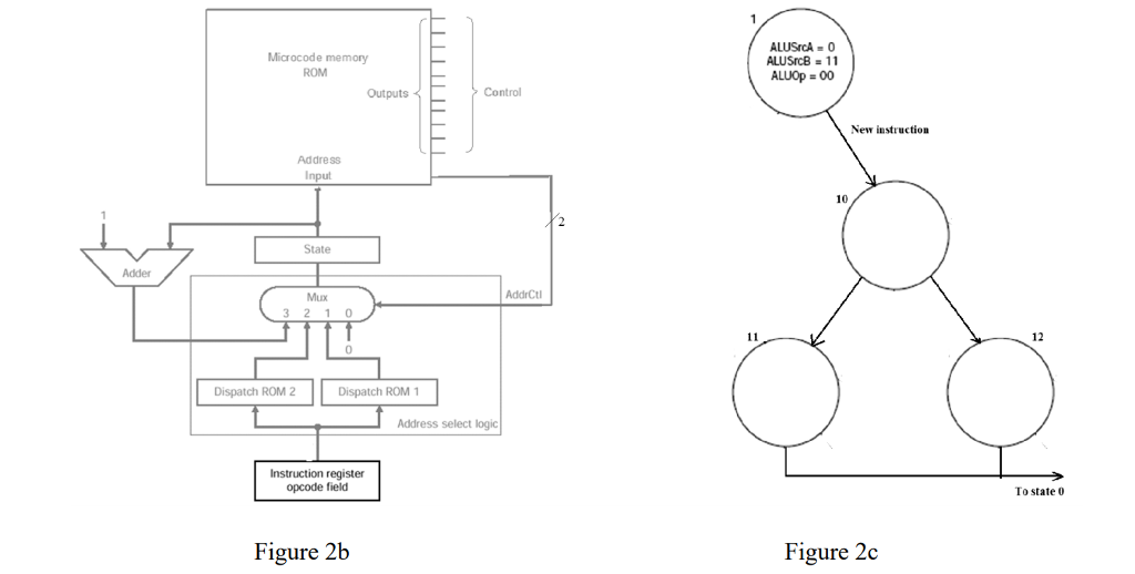
Figure 2b shows a microcode circuit to control a multicycle data path microprocessor. The controller synchronous sequential state machine diagram is shown in figure 4b.
Figure 2b shows a microcode circuit to control a multicycle data path microprocessor. The controller synchronous sequential state machine diagram is shown in figure 4b.
i. With reference to figure 4b, describe the operation of the circuit noting how the ROMs in figure 2b are used.
ii. If a new instruction is to be added that requires additional states as shown in figure 2c, describe how the circuit in figure 2b is modified and used.

Step by Step Solution
There are 3 Steps involved in it
Step: 1

Get Instant Access to Expert-Tailored Solutions
See step-by-step solutions with expert insights and AI powered tools for academic success
Step: 2

Step: 3

Ace Your Homework with AI
Get the answers you need in no time with our AI-driven, step-by-step assistance
Get Started


