

Answered step by step
Verified Expert Solution
Question
1 Approved Answer
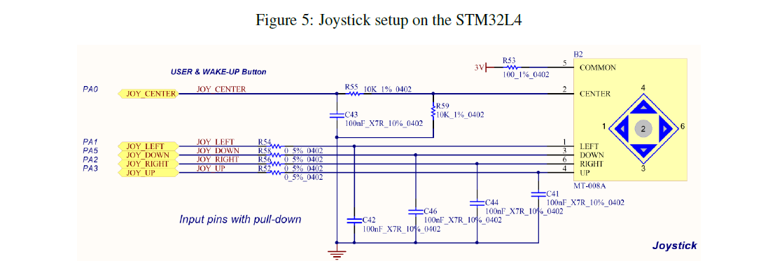
Figure 5: Joystick setup on the STM32L4 R53 3Vw 100_1%_0402 3v1 e me pao2 5 COMMON COMMON USER & WAKE-UP Button JOY CENTER JOY CENTER
Step by Step Solution
There are 3 Steps involved in it
Step: 1

Get Instant Access to Expert-Tailored Solutions
See step-by-step solutions with expert insights and AI powered tools for academic success
Step: 2

Step: 3
Ace Your Homework with AI
Get the answers you need in no time with our AI-driven, step-by-step assistance
Get Started
Advances In Spatial Databases Third International Symposium Ssd 93 Singapore June 1993 Proceedings Lncs 692
Authors: David Abel ,Beng Chin Ooi
1st Edition
3540568697, 978-3540568698