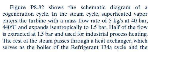
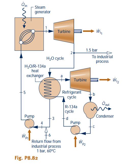
Figure P8.82 shows the schematic diagram of a cogeneration cycle. In the steam cycle, superheated vapor enters the turbine with a mass flow rate


Figure P8.82 shows the schematic diagram of a cogeneration cycle. In the steam cycle, superheated vapor enters the turbine with a mass flow rate of 5 kg/s at 40 bar, 440C and expands isentropically to 1.5 bar. Half of the flow is extracted at 1.5 bar and used for industrial process heating. The rest of the steam passes through a heat exchanger, which serves as the boiler of the Refrigerant 134a cycle and the condenser of the steam cycle. The condensate leaves the heat exchanger as saturated liquid at 1 bar, where it is combined with the return flow from the process, at 60C and 1 bar, before being pumped isentropically to the steam generator pressure. The Refrigerant 134a cycle is an ideal Rankine cycle with refrigerant entering the turbine at 16 bar, 100C and saturated liquid leaving the condenser at 9 bar. Determine, in kW, (a) the rate of heat transfer to the working fluid passing through the steam generator of the steam cycle. (b) the net power output of the binary cycle. (c) the rate of heat transfer to the industrial process. Oin Steam generator Turbine 1.5 bar 2 To industrial . cle process H2O/R-134a heat exchanger W2 Turbine Refrigerant ycle -5 ut R-134a cle Condenser Pump 3 Pump Wp Return flow from industrial process 1 bar, 60C Wp2 Fig. P8.82 LO
Step by Step Solution
3.39 Rating (168 Votes )
There are 3 Steps involved in it
Step: 1
SOLUTION Obtain the proporties from superheated water table for state 1 PI 40 bar a...
See step-by-step solutions with expert insights and AI powered tools for academic success
Step: 2

Step: 3

Ace Your Homework with AI
Get the answers you need in no time with our AI-driven, step-by-step assistance
Get Started


