Question
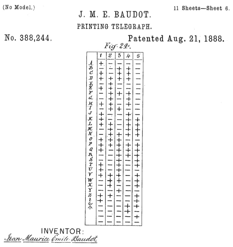
Files: https://drive.google.com/open?id=0ByqLCLGecO3PdlBNTGRHT0F2Tzg 1 Background Baudot Code. The Baudot Code is an early character code in which each character is represented as 5-bit value. The table
Files: https://drive.google.com/open?id=0ByqLCLGecO3PdlBNTGRHT0F2Tzg
1 Background Baudot Code. The Baudot Code is an early character code in which each character is represented as 5-bit value. The table below specifies the code (+ means 1, - means 0).
 Caesar Cipher. Caesar ciphers are simple ciphers wherein characters are permuted. They are easily breakable on their own as underlying character frequencies remain visible, but are often a component of more complex encryption schemes.
2 Function
Your CAESAR module should take one 5-bit Baudot character code and produce the 5-bit Baudot character code corresponding to a Caesar cipher with a right (forward) shift of 6. It should skip non-alphabetic and accented characters in the rotation. For non-alphabetic and accented inputs, the output can be anything. For example Baudot A (10000) should become Baudot G (01010), Baudot V (11101) should become Baudot B (00110), and so on. Be sure to see and skip the accented E in the table above.
3 Quality
Try to minimize gate count. For this assignment, each gate counts as a unit, regardless of the number and negation of its inputs. [Update 9/22: Negated inputs are inputs with bubbles. For example, this allows you to calculate AB with a single AND gate. These can be set in the lower left gate attribute pane in Logisim.] Splitters do not count. 4 Scaffolding
The scaffolding provides a testbench in the main circuit. The testbench will run through a series of test inputs, comparing the design output with the expected output, counting the number of correct and incorrect results (NUM PASS and NUM FAIL respectively). To run the testbench, you must advance a clock (CLK). This can be done either manually (Simulate Tick Once) or automatically (Simulate Ticks Enabled).
For this, and all Logisim assignments, it is critical that the ports on the design module not move from their original locations. To help you track when they have moved, we will always label the expected port locations. If you accidentally move a port from its original position, you may re-position it by right clicking on the design circuit, selecting Edit Circuit Appearance and dragging the port(s) back into position.
The test harness for this assignment tests all 26 letters, compares the output given against the expected output, and counts the passed/failed tests. Note that it expects to find lib3827.circ in the same directory as the main .circ file.
5 Rules and Regulations
- Your design must use ony basic gates AND, OR, NOT, NOR, NAND, XOR, [Update 9/22: or XNOR. You may negate the inputs to these gates in any pattern you wish.] Splitters and pins are fine too.
- Do not change the name or appearance (this includes port locations) of the CAESAR module.
-Simulation of the test harness must halt without error (e.g., oscillations or undefined wire values). Incorrect results (NUM FAIL > 0) are fine.
- Submissions must be made via courseworks. The uploaded .circ filename should not have any spaces [Update 9/26: or non-alphanumeric characters other than a hyphens or underscores. Apart from these restrictions, any filename is fine.]
6 Hints
- Note that the table above numbers the bits in a non-standard way, using 1 for the MSB. The test harness (and Logisim more generally) uses the conventional ordering with bit 4 being the MSB an bit 0 the LSB.
- You might find it easier to get a working design if you re-order the inputs from alphabetical to a standard-ordered truth table.
- Perform checks along the way. For example, decode the truth table outputs to see if the letters are the ones you intend, transcode table to k-maps carefully, and test output bits individually.
- It is not mandatory to use 5-variable k-maps. An alternative approach is to do two 4-variable maps and manually optimize or incorporate the fifth variable.
- Do not let optmization interfere with functionality. Note that any functional circuit will get you a full 70%.
(No Model.) 11 Sheets-Sheet 6. J. M. E. BAUD0T PRINTING TELEGRAPH. No. 388,244 Patented Aug. 21, 1888. INVENTOR (No Model.) 11 Sheets-Sheet 6. J. M. E. BAUD0T PRINTING TELEGRAPH. No. 388,244 Patented Aug. 21, 1888. INVENTORStep by Step Solution
There are 3 Steps involved in it
Step: 1

Get Instant Access to Expert-Tailored Solutions
See step-by-step solutions with expert insights and AI powered tools for academic success
Step: 2

Step: 3

Ace Your Homework with AI
Get the answers you need in no time with our AI-driven, step-by-step assistance
Get Started


