Answered step by step
Verified Expert Solution
Question
1 Approved Answer
finite state machine. need help with the completing the module in verilog OBJECTIVE: Model a 0000111 detector Moore Finite State Machine PROCEDURE: First reference and
 finite state machine. need help with the completing the module in verilog
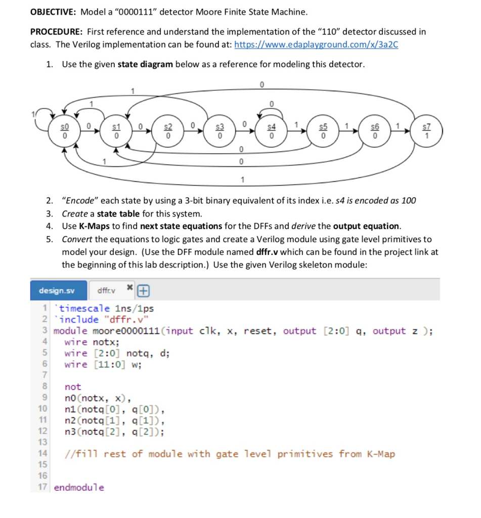
OBJECTIVE: Model a "0000111" detector Moore Finite State Machine PROCEDURE: First reference and understand the implementation of the "110" detector discussed in class. The Verilog implementation can be found at: https://www.edaplayground.com/x/3a2C 1. Use the given state diagram below as a reference for modeling this detector. 2. "Encode" each state by using a 3-bit binary equivalent of its index i.e. s4 is encoded as 100 3. Create a state table for this system 4. Use K-Maps to find next state equations for the DFFs and derive the output equation 5. Convert the equations to logic gates and create a Verilog module using gate level primitives to model your design. (Use the DFF module named dffr.v which can be found in the project link at the beginning of this lab description.) Use the given Verilog skeleton module design.sv timescale 1ns/1ps 2include "dffr.v 3 module moore0000111 (input clk, x, reset, output [2:0] q, output z); 4wire notx; 5 wire [2:0] notq, d; 6 wire [11:0] w; 7 8 not 9 nO (notx, x) 10 n1 (notq [O], q[o]), 11n2 (notq[1], q[1]), 12 n3 (notq [2], q12]); 13 14 //fil1 rest of module with gate level primitives from K-Map 15 16 17 endmodule OBJECTIVE: Model a "0000111" detector Moore Finite State Machine PROCEDURE: First reference and understand the implementation of the "110" detector discussed in class. The Verilog implementation can be found at: https://www.edaplayground.com/x/3a2C 1. Use the given state diagram below as a reference for modeling this detector. 2. "Encode" each state by using a 3-bit binary equivalent of its index i.e. s4 is encoded as 100 3. Create a state table for this system 4. Use K-Maps to find next state equations for the DFFs and derive the output equation 5. Convert the equations to logic gates and create a Verilog module using gate level primitives to model your design. (Use the DFF module named dffr.v which can be found in the project link at the beginning of this lab description.) Use the given Verilog skeleton module design.sv timescale 1ns/1ps 2include "dffr.v 3 module moore0000111 (input clk, x, reset, output [2:0] q, output z); 4wire notx; 5 wire [2:0] notq, d; 6 wire [11:0] w; 7 8 not 9 nO (notx, x) 10 n1 (notq [O], q[o]), 11n2 (notq[1], q[1]), 12 n3 (notq [2], q12]); 13 14 //fil1 rest of module with gate level primitives from K-Map 15 16 17 endmodule
Step by Step Solution
There are 3 Steps involved in it
Step: 1

Get Instant Access to Expert-Tailored Solutions
See step-by-step solutions with expert insights and AI powered tools for academic success
Step: 2

Step: 3
Ace Your Homework with AI
Get the answers you need in no time with our AI-driven, step-by-step assistance
Get Started