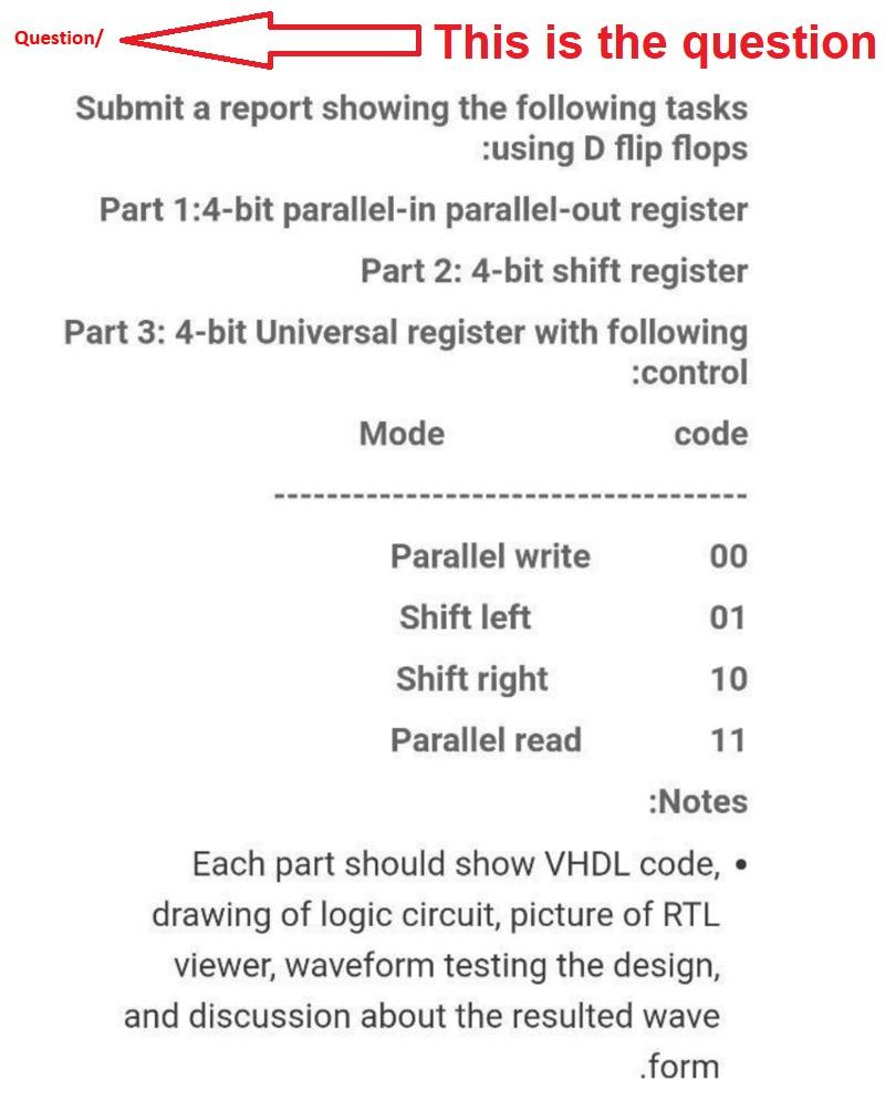
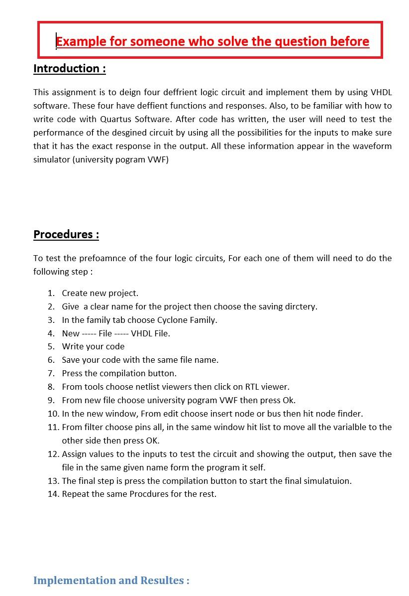
First Picture is the question and the other picture is an example how to solve it
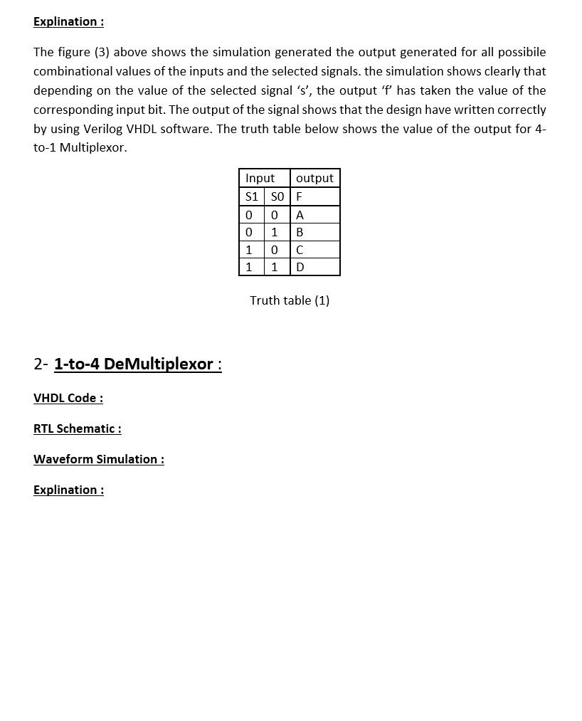
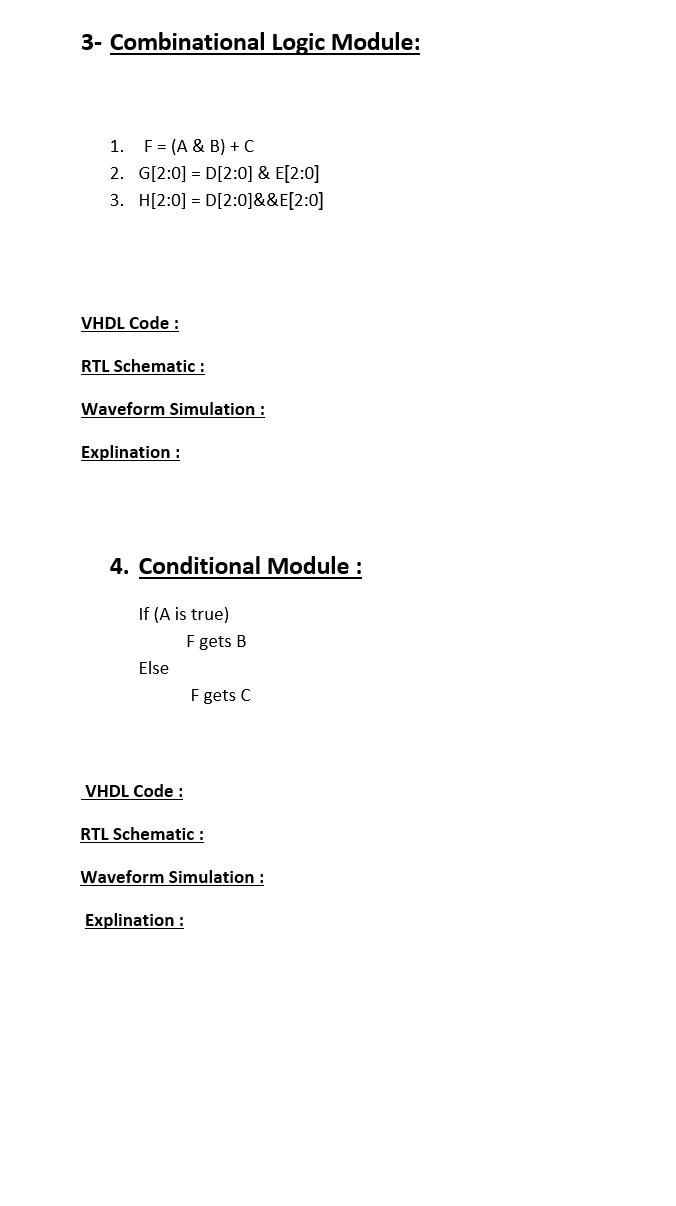
This is the program you should work on it
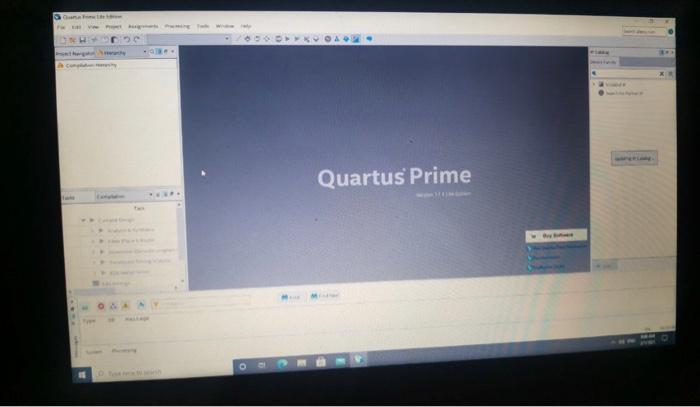
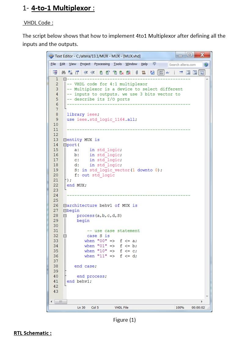
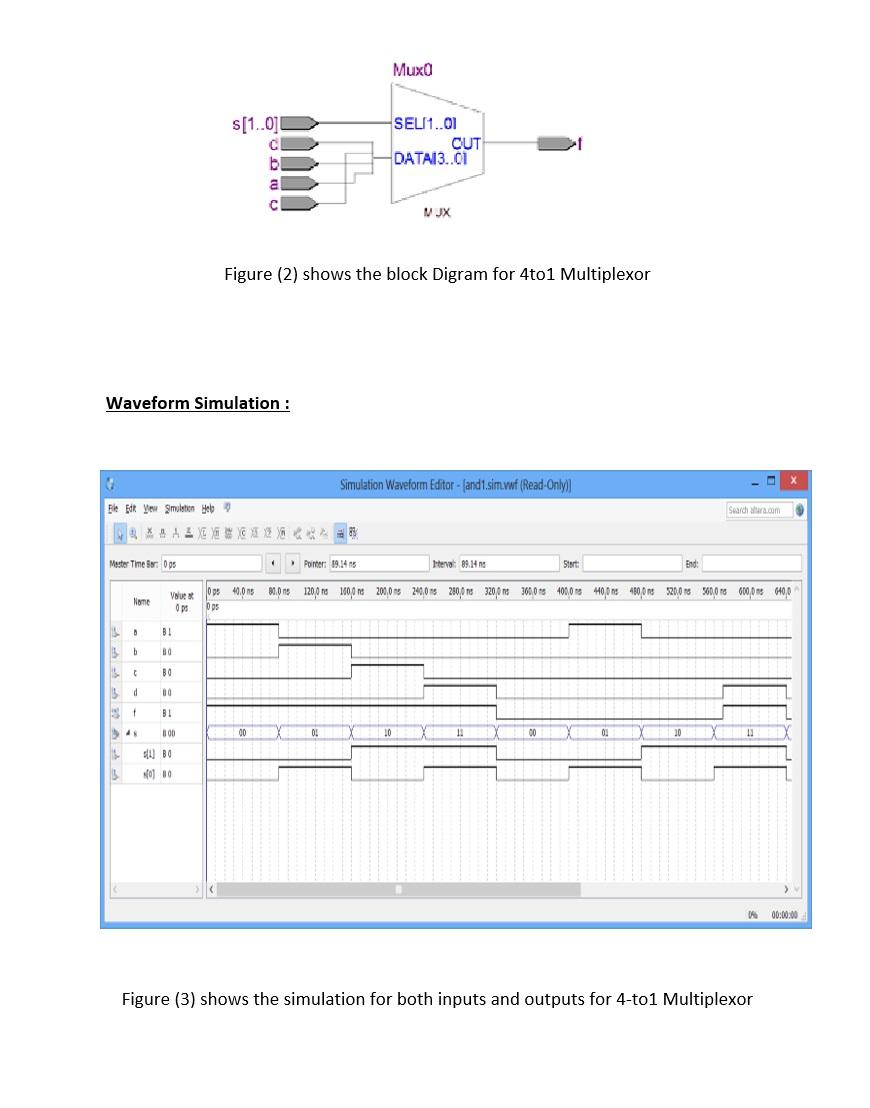
Question/ This is the question Submit a report showing the following tasks :using D flip flops Part 1:4-bit parallel-in parallel-out register Part 2: 4-bit shift register Part 3: 4-bit Universal register with following :control Mode code Parallel write 00 Shift left 01 Shift right 10 Parallel read 11 :Notes Each part should show VHDL code, drawing of logic circuit, picture of RTL viewer, waveform testing the desig and discussion about the resulted wave .form Example for someone who solve the question before Introduction : This assignment is to deign four deffrient logic circuit and implement them by using VHDL software. These four have deffient functions and responses. Also, to be familiar with how to write code with Quartus Software. After code has written, the user will need to test the performance of the desgined circuit by using all the possibilities for the inputs to make sure that it has the exact response in the output. All these information appear in the waveform simulator (university pogram VWF) Procedures : To test the prefoamnce of the four logic circuits, For each one of them will need to do the following step: 1. Create new project. 2. Give a clear name for the project then choose the saving dirctery. 3. In the family tab choose Cyclone Family. 4. New ----- File ----- VHDL File. 5. Write your code 6. Save your code with the same file name. 7. Press the compilation button. 8. From tools choose netlist viewers then click on RTL viewer. 9. From new file choose university pogram VWF then press Ok. 10. In the new window, From edit choose insert node or bus then hit node finder. 11. From filter choose pins all, in the same window hit list to move all the varialble to the other side then press OK. 12. Assign values to the inputs to test the circuit and showing the output, then save the file in the same given name form the program it self. 13. The final step is press the compilation button to start the final simulatuion. 14. Repeat the same Procdures for the rest. Implementation and Resultes : 1- 4-to-1 Multiplexor : VHDL Code: The script below shows that how to implement 4to1 Multiplexor after defining all the inputs and the outputs. Text Editor - C:/altera/13.1/MUX - MUX - [MUX.vhd] Eile Edit View Project Processing Tools Window Help Search altera.com 261 ab/ 1 2 VHDL code for 4:1 multiplexor 3 -- Multiplexor is a device to select different 4 inputs to outputs. we use 3 bits vector to 5 -- describe its I/O ports 6 7 8 library ieee; 9 use ieee.std_logic_1164.all; 10 11 12 13 Bentity MUX is 14 Bport 15 a: in std_logic; 16 b: in std logic; 17 c: in std logic; 18 d: in std logic; 19 S: in std_logic_vector(1 downto 0); 20 f: out std_logic 21 F); 22 end MUX; 23 24 25 26 Barchitecture behvl of MuX is 27 begin 28 process (a, b, c, d, S) 29 begin 30 31 -- use case statement 32 case s is 33 when "00" => f f f f f f f f


