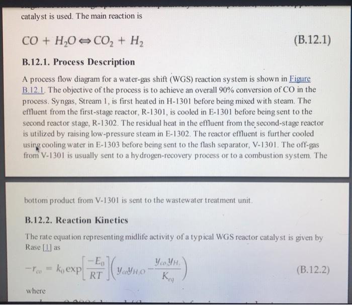
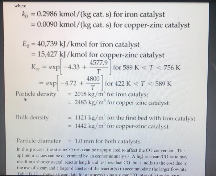
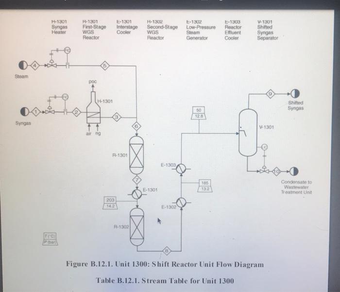
five-plate distillation column (without vapor flow). The distribution of the feeds into the different stages is not shown in Figure B.11 1. and the dimensions of the reactor are taken directly from Chauvel et al. [1] B.11.3. Simulation (CHEMCAD) Hints All the hydrocarbon components used in the simulation can be considered to be well behaved, that is no azeotrope formation. The simulations were carried out using the SRK VLE and enthalpy packages using the CHEMCAD simulator B. 11.4. Reference 1. Chauvel, A., P Leprince, Y Barthel, C Raimbault, and J-P Arlie, Manual of Economic Analysis of Chemical Processes, trans R. Miller and E. B. Miller (New York: McGraw-Hill, 1976), 207-228 B.12. Design of a Shift Reactor Unit to Convert Co To Co2, Unit 1300 The water-gas shift (WGS) reaction has been traditionally used to produce hydrogen from syngas, which comprises CO and II, This process can also be used for producing combustion gas with lower levels of carbon from a carbon-rich synges. The shift reaction is mildly exothermic and equilibrium limited. Therefore, the extent of reaction becomes limited as the temperature increases along the length of the reactor. A two-stage process with interstage cooling is used to achieve the desired extent of conversion. A higher temperature results in a higher reaction rate, and a chromia-promoted iron oxide catalyst is used in the first stage. The second stage operates at a comparatively lower temperature, where a copper-zinc catalyst is used. The main reaction is catalyst is used. The main reaction is CO + H20 CO2 + H2 (B.12.1) B.12.1. Process Description A process flow diagram for a water-gas shift (WGS) reaction system is shown in Figure B.12.1. The objective of the process is to achieve an overall 90% conversion of CO in the process. Syngas, Stream 1, is first heated in H-1301 before being mixed with steam. The effluent from the first-stage reactor, R-1301, is cooled in E-1301 before being sent to the second reactor stage, R-1302. The residual heat in the effluent from the second-stage reactor is utilized by raising low-pressure steam in E-1302. The reactor effluent is further cooled using cooling water in E-1303 before being sent to the flash separator, V-1301. The off-gas from V-1301 is usually sent to a hydrogen-recovery process or to a combustion system. The bottom product from V-1301 is sent to the wastewater treatment unit, B.12.2. Reaction Kinetics The rate equation representing midlife activity of a typical WGS reactor catalyst is given by Rase [1] as -E, V. V, YVHO (B.12.2) RT K -. - k, exp ! ) (7.01 0 Hoteli where where = ko = 0.2986 kmol/(kg cat. s) for iron catalyst = 0.0090 kmol/(kg cat. s) for copper-zinc catalyst E = 40,739 kJ/kmol for iron catalyst 15,427 kJ/kmol for copper-zinc catalyst 4577.9 Ky = exp - 4.33 + for 589 K