Answered step by step
Verified Expert Solution
Question
1 Approved Answer
For the circuit shown in the figure below, the main components are D-Flip-Flops (not latches). Assume that at time 0, the DFFs have the data
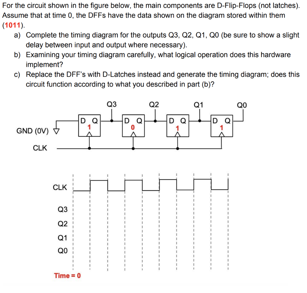
For the circuit shown in the figure below, the main components are D-Flip-Flops (not latches). Assume that at time 0, the DFFs have the data shown on the diagram stored within them (1011). a) Complete the timing diagram for the outputs Q3, Q2, Q1, Q0 (be sure to show a slight delay between input and output where necessary). b) Examining your timing diagram carefully, what logical operation does this hardware implement? c) Replace the DFF's with D-Latches instead and generate the timing diagram; does this circuit function according to what you described in part (b)? Q3 QO Q2 Q1 HID Q HID coat toor GND (ov) + CLK CLK HiHiHii Time = 0
Step by Step Solution
There are 3 Steps involved in it
Step: 1
Get Instant Access to Expert-Tailored Solutions
See step-by-step solutions with expert insights and AI powered tools for academic success
Step: 2
Step: 3
Ace Your Homework with AI
Get the answers you need in no time with our AI-driven, step-by-step assistance
Get Started