For the cross-section shown:
Find and mark Centroid. Determine the moments of inertia about the horizontal and vertical axes through Centroid.
Find principal moments of inertia, find and draw principal axes through Centroid.
Create the Mohr circle.
For the obtained dimensions of the cross-section, determine the functions and draw the diagrams of normal stress b (bending) and t (tension/compression) and resultant stress max =b +t at the most strained cross-section
Determine the functions and draw the diagrams of shear stress at the most strained cross-section of the frame. Determine the reduced stress due to Huber-Mieses-Hencky hypothesis at the centroid.
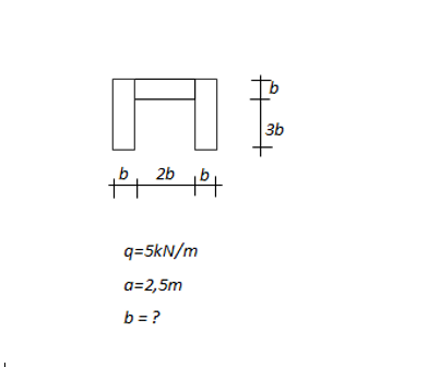
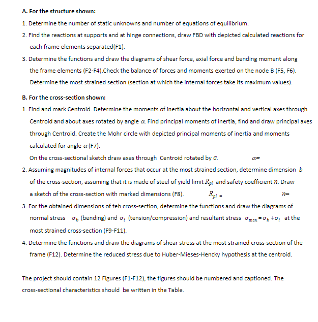
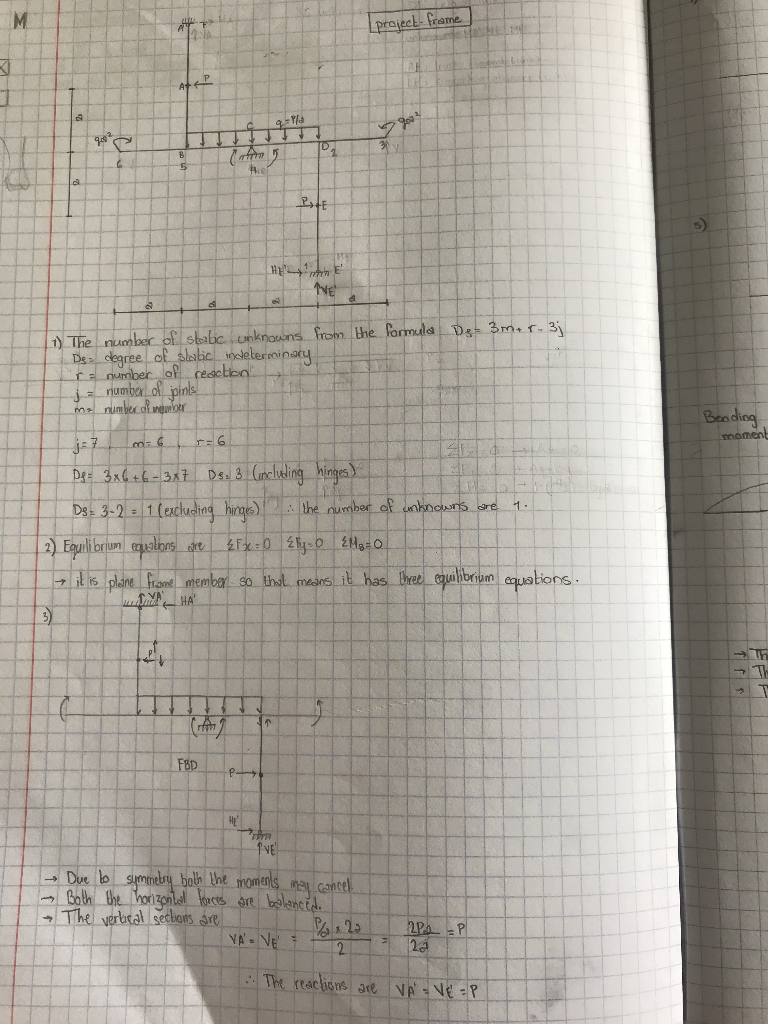
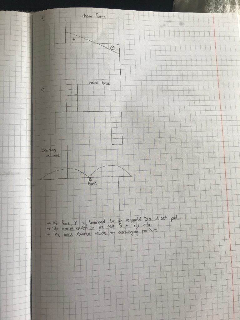
HE 3b b 2b la q=5kN/m a=2,5m b = ? A. For the structure shown: 1. Determine the number of static unknowns and number of equations of equilibrium. 2. Find the reactions at supports and at hinge connections, draw FBD with depicted calculated reactions for each frame elements separated(F1). 3. Determine the functions and draw the diagrams of shear force, axial force and bending moment along the frame elements (F2-F4). Check the balance of forces and moments exerted on the node B (F5, F6). Determine the most strained section (section at which the internal forces take its maximum values). B. For the cross-section shown: 1. Find and mark Centroid. Determine the moments of inertia about the horizontal and vertical axes through Centroid and about axes rotated by angle a Find principal moments of inertia, find and draw principal axes through Centroid. Create the Mohr circle with depicted principal moments of inertia and moments calculated for angle a (F7). On the cross-sectional sketch draw axes through Centroid rotated by a. 2. Assuming magnitudes of internal forces that occur at the most strained section, determine dimension b of the cross-section, assuming that it is made of steel of yield limit Rp and safety coefficient n. Draw a sketch of the cross-section with marked dimensions (FX). Roi = 3. For the obtained dimensions of teh cross-section, determine the functions and draw the diagrams of normal stress op (bending) and 0: (tension/compression) and resultant stress Omax=06+01 at the most strained cross-section (F9-F11). 4. Determine the functions and draw the diagrams of shear stress at the most strained cross-section of the frame (F12). Determine the reduced stress due to Huber-Mieses-Hencky hypothesis at the centroid. 7= The project should contain 12 Figures (F1-F12), the figures should be numbered and captioned. The cross-sectional characteristics should be written in the Table. M AY project- Frame 9-18 D B 5 10 PATE HE IVE 1) The number of stabe unknowns from the formula Dg3m+ r.3j De degree of slabo determinary a number of reactico j = number of pins me number womber Bending m6 momen! 1 Dg= 3x6 +6 - 3x7 Ds. 3 (including hinges) Ds: 3-2 - 1 (excluding hinges) the number of unknowns are 2) Equilibrium equations are F x = 0 {ly: 6 {M=0 - it is plane frame member so that means it has three equilibrium equations. DYNHA FBD ME TVE - Due bo symmetry both the moments may cancel Both the horizontal forces are balanced. The verlical sections are x 22 VA VE 24 28 2 The reactions are VA VE =P shear force + axial force Bonding moment The force P is balanced by the horizontal force at each point. The moment created on the mode B is got only. The most strained seclions are overhanging por Eloms. HE 3b b 2b la q=5kN/m a=2,5m b = ? A. For the structure shown: 1. Determine the number of static unknowns and number of equations of equilibrium. 2. Find the reactions at supports and at hinge connections, draw FBD with depicted calculated reactions for each frame elements separated(F1). 3. Determine the functions and draw the diagrams of shear force, axial force and bending moment along the frame elements (F2-F4). Check the balance of forces and moments exerted on the node B (F5, F6). Determine the most strained section (section at which the internal forces take its maximum values). B. For the cross-section shown: 1. Find and mark Centroid. Determine the moments of inertia about the horizontal and vertical axes through Centroid and about axes rotated by angle a Find principal moments of inertia, find and draw principal axes through Centroid. Create the Mohr circle with depicted principal moments of inertia and moments calculated for angle a (F7). On the cross-sectional sketch draw axes through Centroid rotated by a. 2. Assuming magnitudes of internal forces that occur at the most strained section, determine dimension b of the cross-section, assuming that it is made of steel of yield limit Rp and safety coefficient n. Draw a sketch of the cross-section with marked dimensions (FX). Roi = 3. For the obtained dimensions of teh cross-section, determine the functions and draw the diagrams of normal stress op (bending) and 0: (tension/compression) and resultant stress Omax=06+01 at the most strained cross-section (F9-F11). 4. Determine the functions and draw the diagrams of shear stress at the most strained cross-section of the frame (F12). Determine the reduced stress due to Huber-Mieses-Hencky hypothesis at the centroid. 7= The project should contain 12 Figures (F1-F12), the figures should be numbered and captioned. The cross-sectional characteristics should be written in the Table. M AY project- Frame 9-18 D B 5 10 PATE HE IVE 1) The number of stabe unknowns from the formula Dg3m+ r.3j De degree of slabo determinary a number of reactico j = number of pins me number womber Bending m6 momen! 1 Dg= 3x6 +6 - 3x7 Ds. 3 (including hinges) Ds: 3-2 - 1 (excluding hinges) the number of unknowns are 2) Equilibrium equations are F x = 0 {ly: 6 {M=0 - it is plane frame member so that means it has three equilibrium equations. DYNHA FBD ME TVE - Due bo symmetry both the moments may cancel Both the horizontal forces are balanced. The verlical sections are x 22 VA VE 24 28 2 The reactions are VA VE =P shear force + axial force Bonding moment The force P is balanced by the horizontal force at each point. The moment created on the mode B is got only. The most strained seclions are overhanging por Eloms