

Question: For the drying oil process shown in Appendix B.4, check and validate the design specifications for the following three pieces of equipment against the appropriate
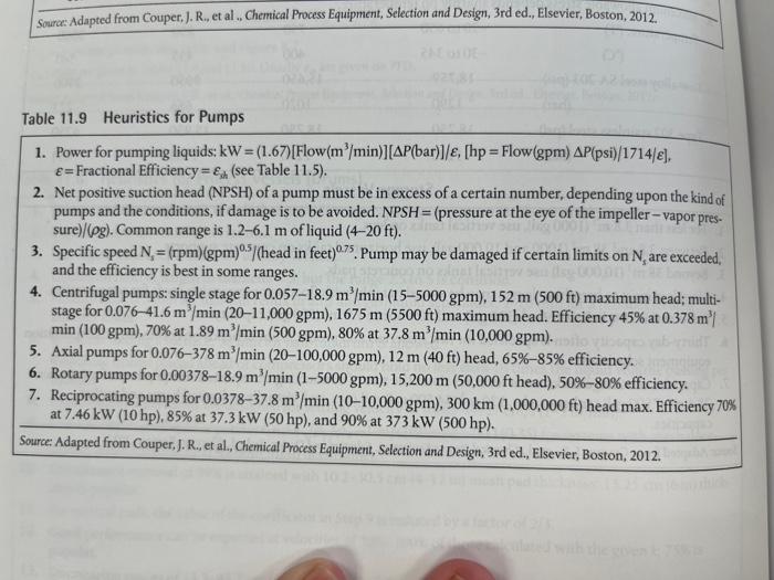
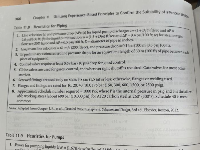
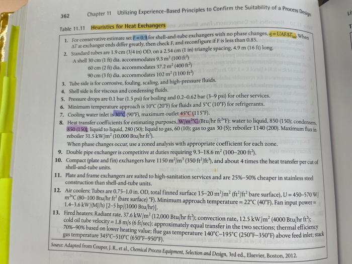
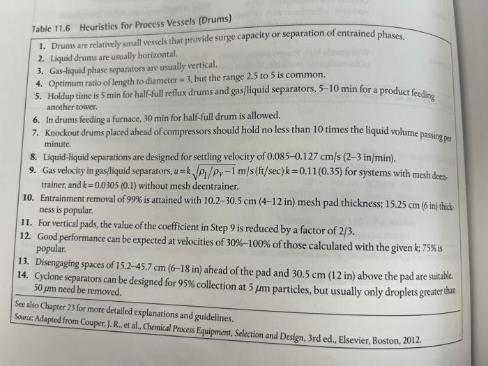
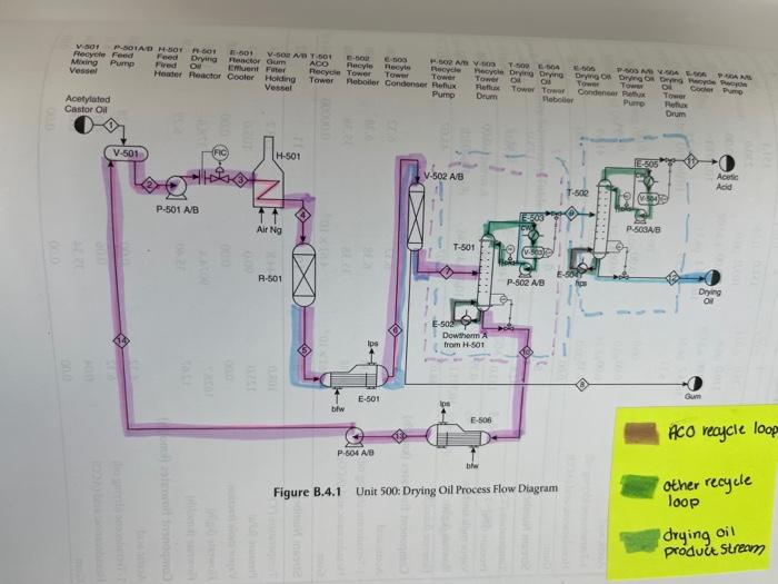
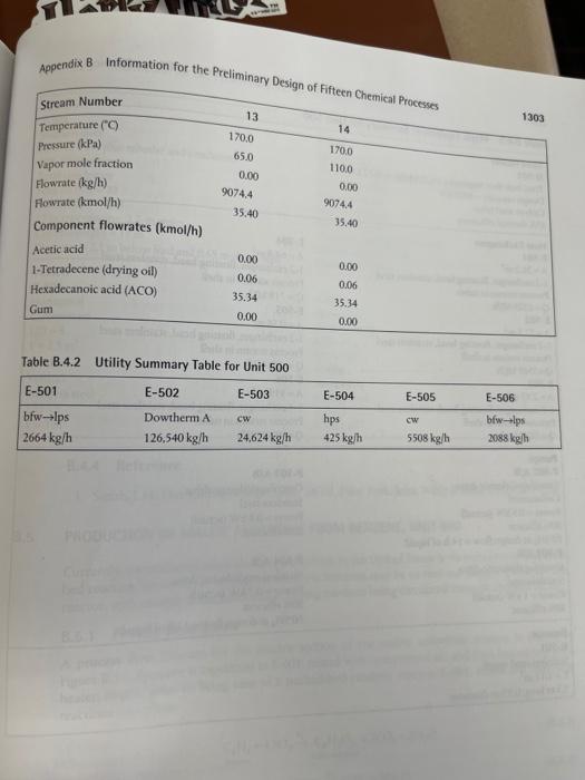
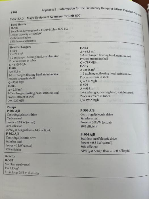
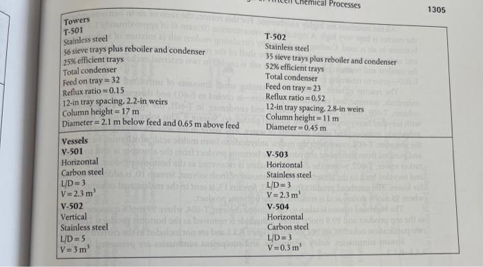
1. Power for pumping liquids: kW=(1.67)[ Flow (m3/min)][P(bar)]/, [hp=Flow(gpm)P(psi)/1714/], = Fractional Efficiency =is( see Table 11.5). 2. Net positive suction head (NPSH) of a pump must be in excess of a certain number, depending upon the kind of pumps and the conditions, if damage is to be avoided. NPSH = (pressure at the eye of the impeller-vapor pressure) /(g). Common range is 1.26.1m of liquid (4-20 ft). 3. Specific speed N5=(rpm)(gpm)0.5/ (head in feet 0.75. Pump may be damaged if certain limits on Ns are exceeded, and the efficiency is best in some ranges. 4. Centrifugal pumps: single stage for 0.05718.9m3/min(155000gpm),152m (500 ft) maximum head; multistage for 0.07641.6m3/min(2011,000gpm),1675m(5500ft) maximum head. Efficiency 45% at 0.378m3 min(100gpm),70% at 1.89m3/min(500gpm),80% at 37.8m3/min(10,000gpm). 5. Axial pumps for 0.076378m3/min(20100,000gpm),12m(40ft) head, 65%85% efficiency. 6. Rotary pumps for 0.0037818.9m3/min(15000gpm),15,200m (50,000 ft head), 50%80% efficiency. 7. Reciprocating pumps for 0.037837.8m3/min(1010,000gpm),300km(1,000,000ft) head max. Efficiency 70% at 7.46kW(10hp),85% at 37.3kW(50hp), and 90% at 373kW(500hp). Source: Adapted from Couper, J. R., et al., Chemical Process Equipment, Selection and Design, 3rd ed., Elsevier, Boston, 2012. 1. Line velocities (u) and pressure drop (P) : (a) for liquid pump discharge: u=(5+D/3)ft/sec and P= 2.0psi/100ft; (b) for liquid pump suction: u=(1.3+D/6)ft/sec and P=0.4psi/100ft;(c) for steam or gas flow: u=20ft/sec and P=0.5psi/100ft,D= diameter of pipe in inches. 2. Gas / steam line velocities =61m/s(200ft/sec), and pressure drop =0.1bar/100m(0.5psi/100ft). 3. In preliminary estimates set line pressure drops for an equivalent length of 30m(100ft) of pipe between cach piece of equipment. 4. Control valves require at least 0.69 bar ( 10 psi) drop for good control. 5. Globe valves are used for gases, control, and wherever tight shutoff is required. Gate valves for most other services. 6. Screwed fittings are used only on sizes 3.8cm (1.5 in) or less; otherwise, flanges or welding used. 7. Flanges and fittings are rated for 10,20,40,103,175 bar (150,300,600,1500, or 2500psig). 8. Approximate schedule number required =1000P/S, where P is the internal pressure in p sig and S is the allowable working stress [about 690bar(10,000psi)] for A120 carbon steel at 260(500F). Schedule 40 is most common. Table 11.11 Heuristics for Heat Exchangers 1. For conservative estimate set E=0.9 for shell-and-tube exchangers with no phase changes, q=UAFThetWhen T at exchanger ends differ greatly, then check F, and reconfigure if F is less than 0.85 . 2. Standard tubes are 1.9cm(3/4in)OD, on a 2.54cm(1in) triangle spacing. 4.9m(16ft) long. A shell 30cm ( ft) dia, accommodates 9.3m2(100ft) 60cm(2ft) dia, accommodates 37.2m2(400ft2) 90cm (3 ft ) dia. accommodates 102m2(1100ft2) 3. Tube side is for corrosive, fouling, scaling, and high-pressure fluids. 4. Shell side is for viscous and condensing fluids. 5. Pressure drops are 0.1 bar ( 1.5psi) for boiling and 0.20.62 bar (3-9 psi) for other services. 6. Minimum temperature approach is 10C(20F) for fluids and 5C(10F) for refrigerants. 7. Cooling water inlet is 30C(90F), maximum outlet 45C(115F). 8. Heat transfer coefficients for estimating purposes, W/m20C(Btu/hrft2F) : water to liquid, 850(150) : condensers, 850 (150) liquid to liquid, 280 (50); liquid to gas, 60 (10); gas to gas 30 (5); reboiler 1140 (200). Maximum fluxin reboiler 31.5kW/m2(10,000Btu/hrft2). When phase changes occur, use a zoned analysis with appropriate coefficient for each zone. 9. Double pipe exchanger is competitive at duties requiring 9.318.6m2(100200ft2). 10. Compact (plate and fin) exchangers have 1150m2/m3(350ft2/ft3), and about 4 times the heat transfer per cut of shell-and-tube units. 11. Plate and frame exchangers are suited to high-sanitation services and are 25%50% cheaper in stainless steel construction than shell-and-tube units. 12. Air coolers: Tubes are 0.751.0 in. OD, total finned surface 1520m2/m2(ft2/ft2 bare surface), U=450570W m20C(80100 Btu/hr ft2 (bare surface) F. Minimum approach temperature =22C(40F). Fan input power = 1.43.6kW/(M)/h)[25hp/(1000Btu/hr)]. 13. Fired heaters: Radiant rate, 37.6kW/m2(12,000Btu/hrft2); convection rate, 12.5kW/m2(4000Btu/hrft2); cold oil tube velocity =1.8m/s(6ft/sec); approximately equal transfer in the two sections; thermal efficiency 70%90% based on lower heating value; flue gas temperature 140C195C(250F350F) above feed inlet; stack gas temperature 345C510C(650F950F). Surce Adapted from Couper, J. R, et al, Chemical Process Equipment, Selection and Design, 3rd ed., Elsevier, Boston, 2012. Table 11.6 Heuristics for Process Vessels (Drums) 1. Drums are relatively small vessels that provide surge capacity or separation of entrained phases. 2. Liquid drums are usually horizontal. 3. Gas-liquid phase separators are usually vertical. 4. Optimum ratio of length to diameter =3, but the range 2.5 to 5 is common. 5. Holdup time is 5 min for half-full reflux drums and gas/liquid separators, 510min for a product feeding another tower. 6. In drums feeding a furnace, 30min for half-full drum is allowed. 7. Knockout drums placed ahead of compressors should hold no less than 10 times the liquid volume passing per minute. 8. Liquid-liquid separations are designed for settling velocity of 0.0850.127cm/s(23in/min). 9. Gas velocity in gas/liquid separators, u=kl/1m/s(ft/sec)k=0.11(0.35) for systems with mesh deentrainer, and k=0.0305(0.1) without mesh deentrainer. 10. Entrainment removal of 99% is attained with 10.230.5cm (4-12 in) mesh pad thickness; 15.25cm (6 in) thickness is popular. 11. For vertical pads, the value of the coefficient in Step 9 is reduced by a factor of 2/3. 12. Good performance can be expected at velocities of 30%100% of those calculated with the given k;75% is popular. 13. Disengaging spaces of 15.245.7cm(618in) ahead of the pad and 30.5cm(12in) above the pad are suitable. 14. Cyclone separators can be designed for 95% collection at 5m particles, but usually only droplets greater than 50m need be removed. See also Chapter 23 for more detailed explanations and guidelines. Source: Adapted from Couper, J. R., et al., Chemical Process Equipment, Selection and Design, 3rd ed., Elsevier, Boston, 2012. Aninendix B Information for the Preliminary Design of Fifteen Cha. Appendix B Information for the Preliminaru naas Table B.4.2 Utility Summary Table for Unit 500 1304 Table 8.4.3 Major Equip Appendix B Information for the Preliminary Design of Fifteen Chemical Peteden. Fired Heater H-501 Total heat duty required =13,219M/h=3672kW Design capacity =4000kW Carbon steel tubes 85% thermal efficiency Heat Exchangers E-504 E.501 A=64.8m2 A=26.2mm2 1-2 exchanger, floating head, stainless steel 1-2 exchanger, floating head, stainless steel Process stram in tubes Process stream in shell Q=6329M/h Q=719M/h E-502 E-505 A=57,5m2 A=0.58m2 1-2 exchanger, floating head, stainless steel 1-2 exchanger, floating head, stainless steel Process stream in shell Process stream in shell Q=5569M]/h Q=230M//h E-503 E-506 A=2.95m2 A=919m2 12 exchanger, floating head, stainless steel 1-4 exchanger, floating head, stainless steel Process stream in shell Process stream in tubes Q=1029MJ/h Q=4962M/h Pumps P-501 A/B P-503 A/B Centrifugal/electric drive Centrifugal/electric drive Carbon steel Stainless steel Power =0.9kW (actual) Power =0.8kW (actual) 80 efficient 80% efficient NPSHk at design flow =14ft of liquid P502A/B P-504 A/B Centrifugal/electric drive Stainless steel/electric drive Stainless steel Power =0.3kW (actual) Power =1kW (actual) 80% efficient 80% efficient NPSH2 at design flow =12 ft of liquid Reactor R.501 Stainless steel vessel V=1.15m3 5.3m long 0.53mn diameter \begin{tabular}{|ll|} \hline Towers & \\ \hline T-501 & \\ stainless steel & T-502 \\ 56 sieve trays plus reboiler and condenser & Stainless steel \\ 25% efficient trays & 35 sieve trays plus reboiler and condenser \\ Total condenser & 52% efficient trays \\ Feed on tray =32 & Total condenser \\ Reflux ratio =0.15 & Feed on tray =23 \\ 12 -in tray spacing, 2.2 -in weirs & Reflux ratio =0.52 \\ Column height =17m & 12 -in tray spacing. 2.8 -in weirs \\ Diameter =2.1m below feed and 0.65m above feed & Column height =11m \\ \hline Vessels & Diameter =0.45m \\ V-501 & \\ Horizontal & V-503 \\ Carbon steel & Horizontal \\ V/D =3 & Stainless steel \\ V=2.3m3 & L/D=3 \\ V-502 & V =2.3m3 \\ Vertical & V- 504 \\ Stainless steel & Horizontal \\ L/D=5 & Carbon steel \\ V=3m3 & UD =3 \\ \hline \end{tabular}
Step by Step Solution
There are 3 Steps involved in it

Get step-by-step solutions from verified subject matter experts