Answered step by step
Verified Expert Solution
Question
1 Approved Answer
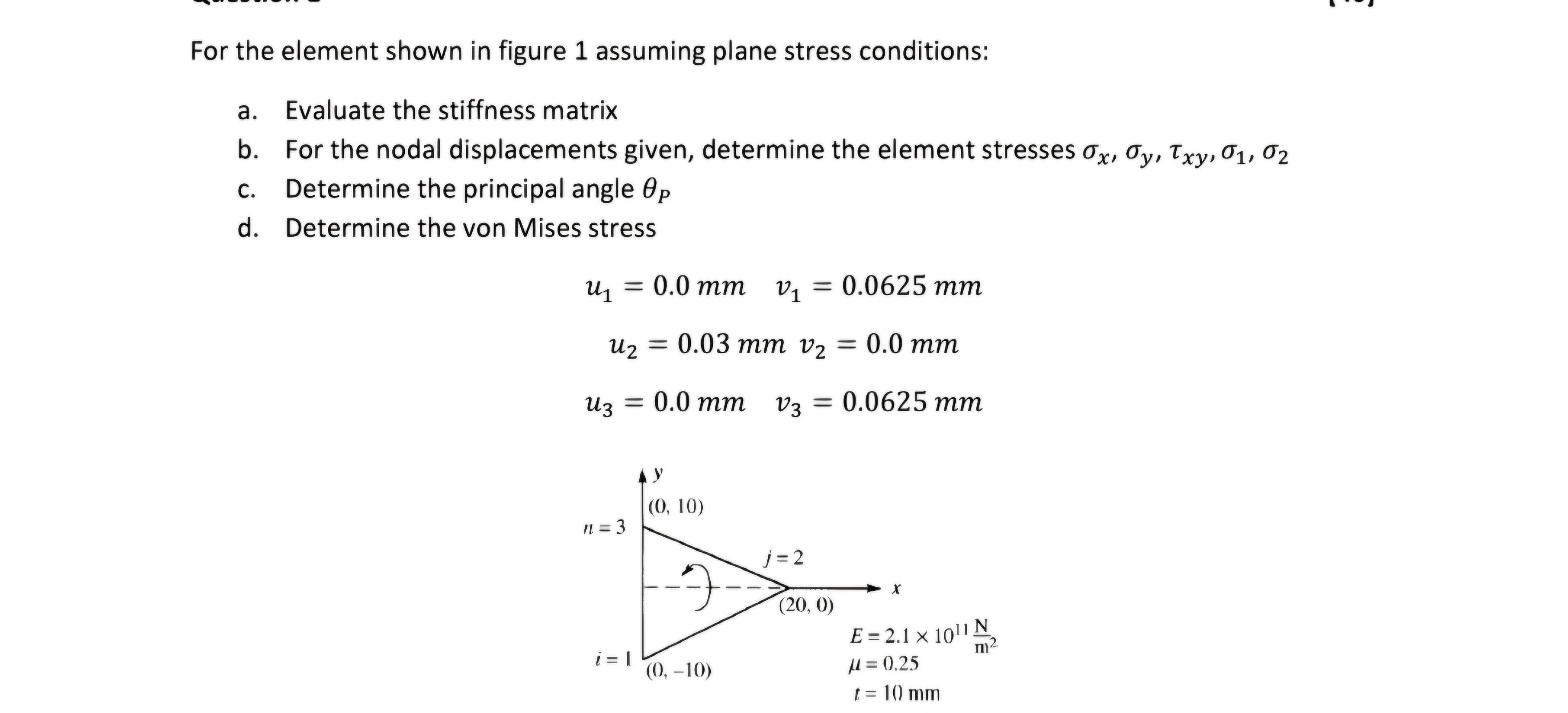
For the element shown in figure 1 assuming plane stress conditions: a. b. For the nodal displacements given, determine the element stresses Ox, Oy,

For the element shown in figure 1 assuming plane stress conditions: a. b. For the nodal displacements given, determine the element stresses Ox, Oy, Txy, 01, 02 C. Evaluate the stiffness matrix. Determine the principal angle Op d. Determine the von Mises stress P u = 0.0 mm V = 0.0625 mm 01 u = 0.03 mm v = 0.0 mm u3 = 0.0 mm v3 = 0.0625 mm (0, 10) n = 3 j=2 (20, 0) i=1 (0, -10) E = 2.1 1011 N = 0.25 t = 10 mm m
Step by Step Solution
There are 3 Steps involved in it
Step: 1
To solve this problem we will follow a series of steps for each part Lets dive into the details a Ev...
Get Instant Access to Expert-Tailored Solutions
See step-by-step solutions with expert insights and AI powered tools for academic success
Step: 2

Step: 3

Ace Your Homework with AI
Get the answers you need in no time with our AI-driven, step-by-step assistance
Get Started


