

Answered step by step
Verified Expert Solution
Question
1 Approved Answer
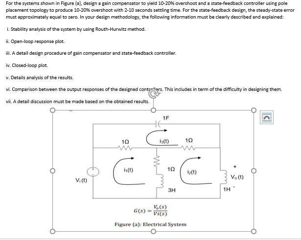
For the systems shown in Figure (a), design a gain compensator to yield 10-20% overshoot and a state-feedback controller using pole placement topology to produce
Step by Step Solution
There are 3 Steps involved in it
Step: 1

Get Instant Access to Expert-Tailored Solutions
See step-by-step solutions with expert insights and AI powered tools for academic success
Step: 2

Step: 3
Ace Your Homework with AI
Get the answers you need in no time with our AI-driven, step-by-step assistance
Get Started
Management Audits For Excellence
Authors: Dorsey J. Talley
1st Edition
0873890396, 978-0873890397