For this exercise your Answer will be to modify only the statements of the Test Bench indicated below that reference the new Model to be tested and
those Test Bench statements that should be modified to complete the Test Case #3 and Test Case #4 for the new Model.
To simplify your task and avoid too much typing just write the VHDL code lines for :
- Test Bench Model Name : (Should follow same format as the existing name, now testing an 11-bit Shift Register)
- Eleven Bit Register Component Declaration (just the lines that change): (There are at least two lines that should change)
- The Assertion at the end of Test Case #3: (See Note_3 below.) and (The assertion should have the Assert, Report, Severity sections)
- The Assertion at the end of Test Case #4: (See Note_4 below.) and (The assertion should have the Assert, Report, Severity sections)
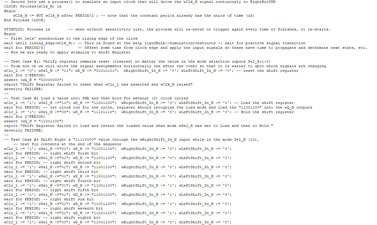
Note_3: Assume that the eleven bits been shifted right are "11 00110011 0"
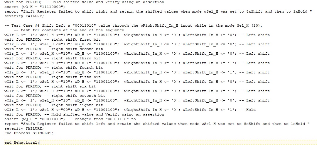
Note_4: Assume that the eleven bits been shifted left are "11 01110111 0"
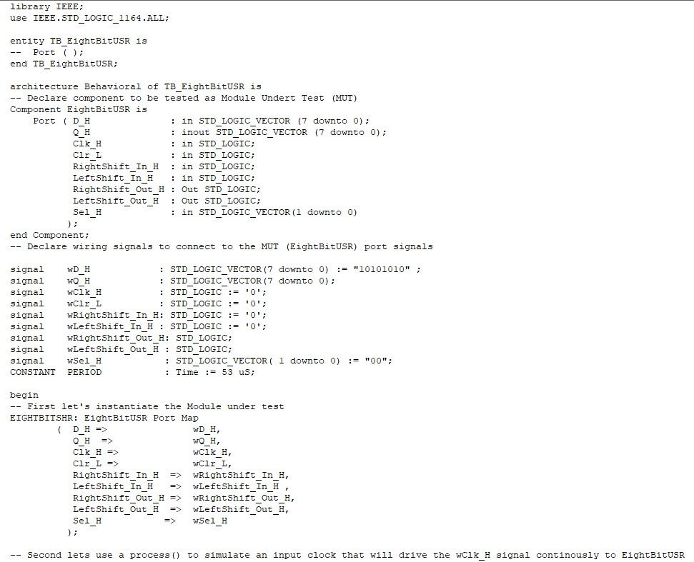
library IEEE; use IEEE.STD_LOGIC_1164.ALL; entity TB_EightBituse is -- Port 7); end TB_EightBitUSR; . CIKH Clr_L : : : architecture Behavioral of TB_EightBitUse is -- Declare component to be tested as Module Undert Test (MUT) Component EightBituse is Port (D_H in STD_LOGIC_VECTOR (7 downto 0); : inout STD_LOGIC_VECTOR (7 downto 0); : in STD_LOGIC; in STD LOGIC; Right Shift_In_H : in STD LOGIC; LeftShift In H in STD_LOGIC; Right Shift_out_u : Out STD_LOGIC; LeftShift_out_ : Out STD LOGIC; Sel_H in STD_LOGIC_VECTOR (1 downto 0) ); end Component; -- Declare wiring signals to connect to the MUT (EightBitUSR) port signals signal : STD_LOGIC_VECTOR (7 downto 0) := "10101010" ; signal : STD LOGIC VECTOR (7 downto 0); wck_1 : STD LOGIC := '0'; WCIEL : STD LOGIC := '0'; signal wRightshift_In_H: STD LOGIC := '0'; signal wLeftShift_In_ : STD LOGIC := '0'; signal wRight Shift_Out H: STD LOGIC; signal WLeft Shift Out H: STD LOGIC; signal wSel H : STD_LOGIC_VECTOR( 1 downto 0) := "00"; CONSTANT PERIOD : Time := 53 us; signal signal begin -- First let's instantiate the Module under test EIGHTBITSHR: EightBitUSR Port Map DH => WD H, OH WQ H, Cik H => wcik H, wClr L, Right Shift In H wRight Shift_In_H, LeftShift_In_H WLeft Shift In H Right Shift Out H => WRight Shift Out H, LeftShift Out H wLeftShift_out_H, Sel_H wSel_H CIEL -- Second lets use a process() to simulate an input clock that will drive the wcik_H signal continously to EightBitUSR -- Second lets use a process () to simulate an input clock that will drive the wcik_H signal continously to EightBitUSR CLOCK: Process (wCik_H) is Begin wClk_H SimulationConstructs -> wait for positive signal transition wait for PERIOD/5; -- Offset some time from clock edge and apply the input signals so these have time to propagate and determine next state, -- Now we are ready to apply stimulus to shift Register etc. -- Test Case #1: Verify register remains reset (cleared) no matter the value in the mode selection inputs Sel_H(1:0) -- From now on we will write the signal assignments horizontally one after the other so that it is easier to spot which signals are changing wCir_L = '0'; wSel_H WD H, OH WQ H, Cik H => wcik H, wClr L, Right Shift In H wRight Shift_In_H, LeftShift_In_H WLeft Shift In H Right Shift Out H => WRight Shift Out H, LeftShift Out H wLeftShift_out_H, Sel_H wSel_H CIEL -- Second lets use a process() to simulate an input clock that will drive the wcik_H signal continously to EightBitUSR -- Second lets use a process () to simulate an input clock that will drive the wcik_H signal continously to EightBitUSR CLOCK: Process (wCik_H) is Begin wClk_H SimulationConstructs -> wait for positive signal transition wait for PERIOD/5; -- Offset some time from clock edge and apply the input signals so these have time to propagate and determine next state, -- Now we are ready to apply stimulus to shift Register etc. -- Test Case #1: Verify register remains reset (cleared) no matter the value in the mode selection inputs Sel_H(1:0) -- From now on we will write the signal assignments horizontally one after the other so that it is easier to spot which signals are changing wCir_L = '0'; wSel_H