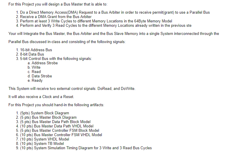
For this Project you will design a Bus Master that is able to 1. Do a Direct Memory Access(DMA) Request to a Bus Arbiter in order to receive permit(grant) to use a Parallel Bus 2. Receive a DMA Grant from the Bus Arbiter 3. Perform at least 3 Write Cycles to different Memory Locations in the 64Byte Memory Model 4. Perform and Verify 3 Read Cycles to the different Memory Locations already written in the previous ste Your will Integrate the Bus Master, the Bus Arbiter and the Bus Slave Memory into a single System interconnected through the Parallel Bus discussed in-class and consisting of the following signals 1. 16-bit Address Bus 2. 8-bit Data Bus 3. 5-bit Control Bus with the following signals a. Address Strobe b. Write C. Read d. Data Strobe e. Ready This System will receive two external control signals: DoRead, and DoWrite It will also receive a Clock and a Reset. For this Project you should hand-in the following artifacts 1. (5pts) System Block Diagram 2. (5 pts) Bus Master Block Diagram 3. (5 pts) Bus Master Data Path Block Model 4. (10 pts) Bus Master Data Path VHDL Model 5. (5 pts) Bus Master Controller FSM Block Model 6. (10 pts) Bus Master Controller FSM VHDL Model 7. (10 pts) System VHDL Model 8. (10 pts) System TB Model 9. (10 pts) System Simulation Timing Diagram for 3 Write and 3 Read Bus Cycles For this Project you will design a Bus Master that is able to 1. Do a Direct Memory Access(DMA) Request to a Bus Arbiter in order to receive permit(grant) to use a Parallel Bus 2. Receive a DMA Grant from the Bus Arbiter 3. Perform at least 3 Write Cycles to different Memory Locations in the 64Byte Memory Model 4. Perform and Verify 3 Read Cycles to the different Memory Locations already written in the previous ste Your will Integrate the Bus Master, the Bus Arbiter and the Bus Slave Memory into a single System interconnected through the Parallel Bus discussed in-class and consisting of the following signals 1. 16-bit Address Bus 2. 8-bit Data Bus 3. 5-bit Control Bus with the following signals a. Address Strobe b. Write C. Read d. Data Strobe e. Ready This System will receive two external control signals: DoRead, and DoWrite It will also receive a Clock and a Reset. For this Project you should hand-in the following artifacts 1. (5pts) System Block Diagram 2. (5 pts) Bus Master Block Diagram 3. (5 pts) Bus Master Data Path Block Model 4. (10 pts) Bus Master Data Path VHDL Model 5. (5 pts) Bus Master Controller FSM Block Model 6. (10 pts) Bus Master Controller FSM VHDL Model 7. (10 pts) System VHDL Model 8. (10 pts) System TB Model 9. (10 pts) System Simulation Timing Diagram for 3 Write and 3 Read Bus Cycles