

GCD circuit calculates the greatest common divisor (GCD) of two binary positive 4-bit numbers. The operand registers, p and q, are initialized with the
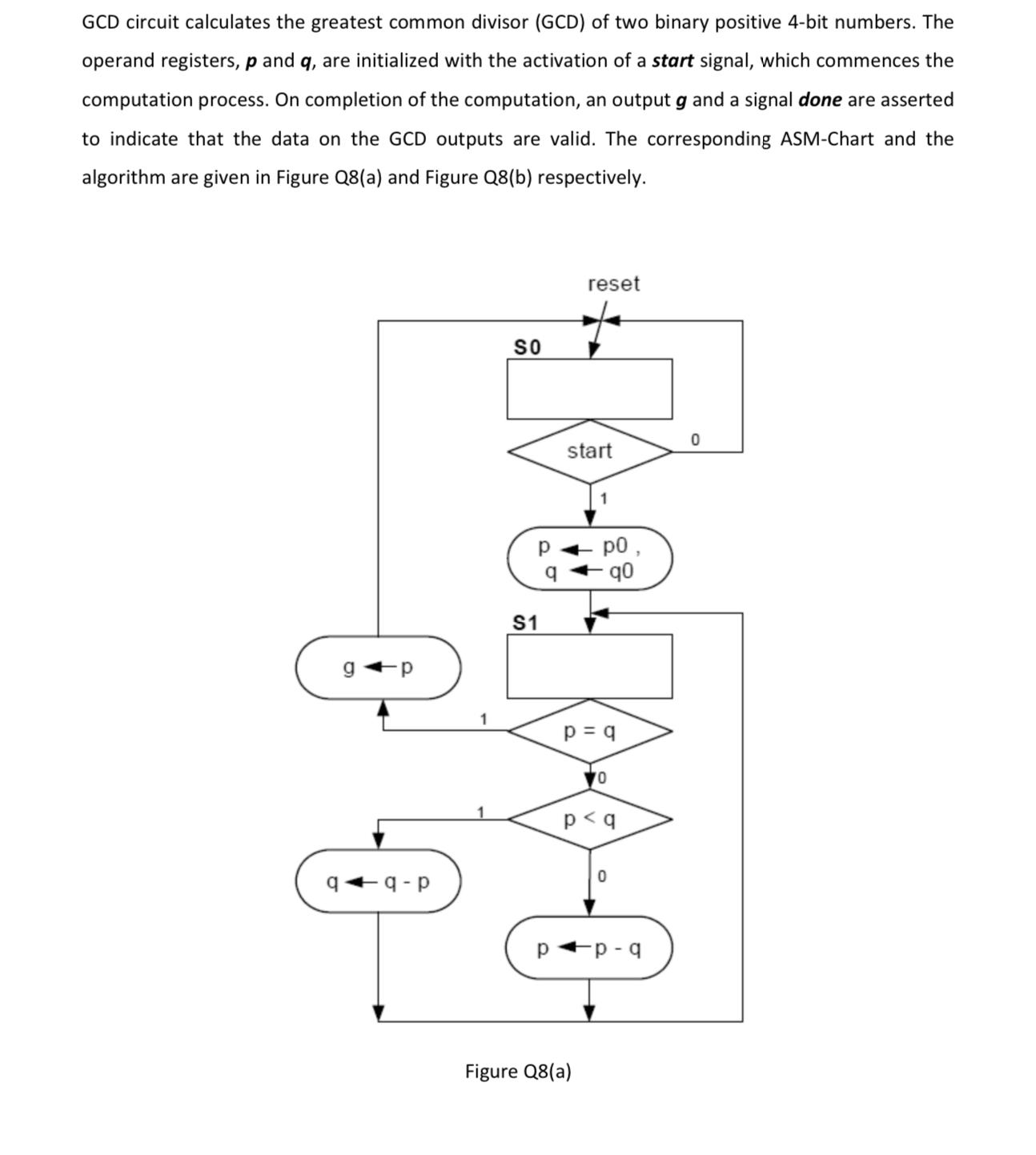
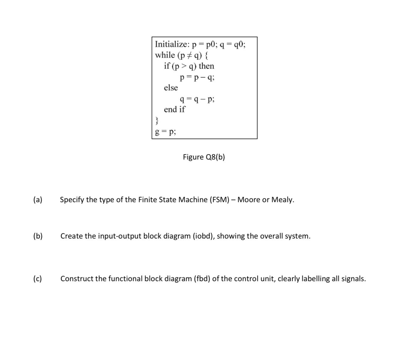
GCD circuit calculates the greatest common divisor (GCD) of two binary positive 4-bit numbers. The operand registers, p and q, are initialized with the activation of a start signal, which commences the computation process. On completion of the computation, an output g and a signal done are asserted to indicate that the data on the GCD outputs are valid. The corresponding ASM-Chart and the algorithm are given in Figure Q8(a) and Figure Q8(b) respectively. g q-p SO S1 q reset start -q0 p = q Figure Q8(a) 0 p (a) (b) (c) Initialize: p = p0; q = q0; while (p #q) { if (p > q) then p=p-q; else 9=9-p; end if g= p; Figure Q8(b) Specify the type of the Finite State Machine (FSM) - Moore or Mealy. Create the input-output block diagram (iobd), showing the overall system. Construct the functional block diagram (fbd) of the control unit, clearly labelling all signals.
Step by Step Solution
3.52 Rating (162 Votes )
There are 3 Steps involved in it
Step: 1
To determine the number of teeth on all the wheels and the exact pitch circle diameter of A we can f... View full answer

Get step-by-step solutions from verified subject matter experts
100% Satisfaction Guaranteed-or Get a Refund!
Step: 2Unlock detailed examples and clear explanations to master concepts

Step: 3Unlock to practice, ask and learn with real-world examples
See step-by-step solutions with expert insights and AI powered tools for academic success
-
 Access 30 Million+ textbook solutions.
-
Ask unlimited questions from AI Tutors.
-
Order free textbooks.
-
100% Satisfaction Guaranteed-or Get a Refund!
Claim Your Hoodie Now!
Authors: Y. Daniel Liang
10th Edition
133761312, 978-0133761313

Study Smart with AI Flashcards
Access a vast library of flashcards, create your own, and experience a game-changing transformation in how you learn and retain knowledge
Explore Flashcards

