

Question: generally, please write three major parts: the cmake file, the assembler and the simulator. Please write in CPP language and male sure the whole program
generally, please write three major parts: the cmake file, the assembler and the simulator. Please write in CPP language and male sure the whole program can run without bugs. thank you very much.
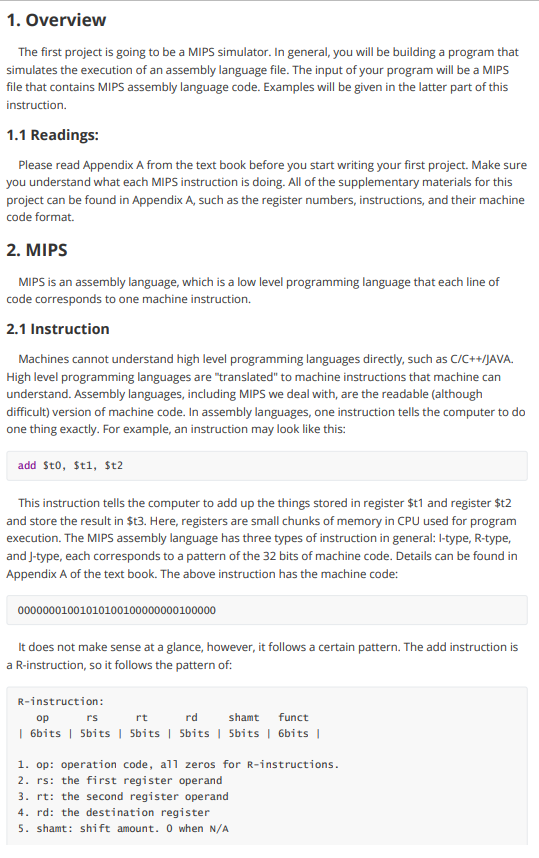
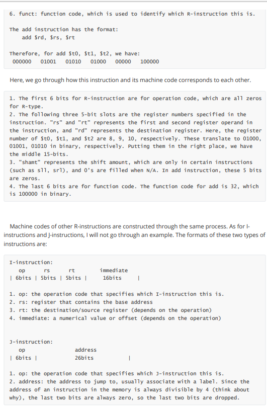
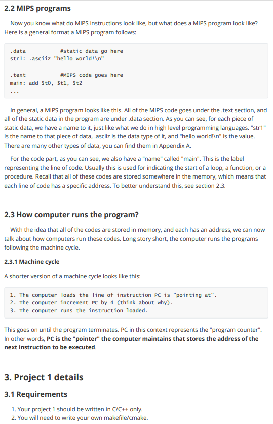
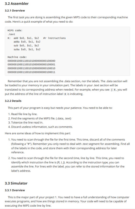
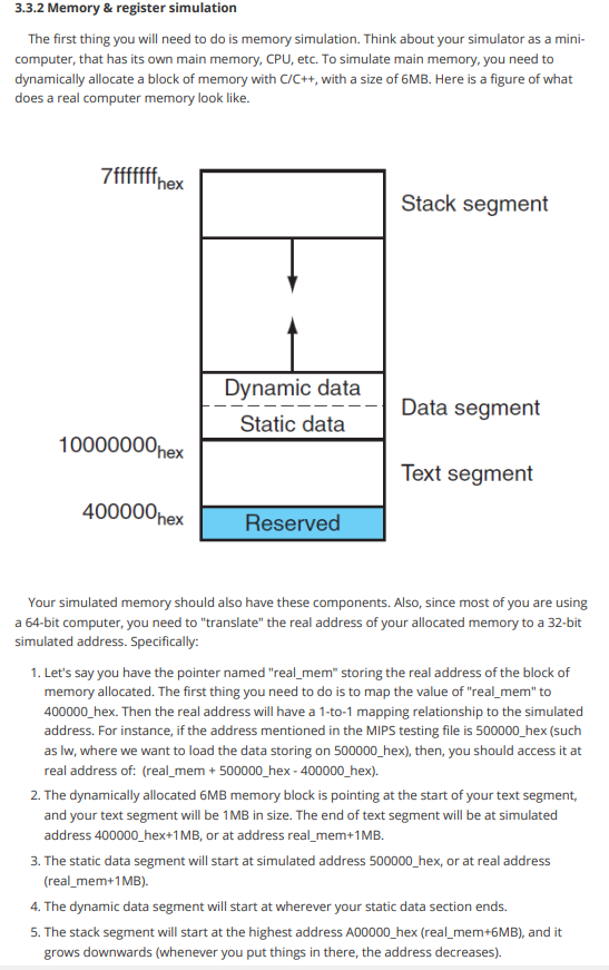
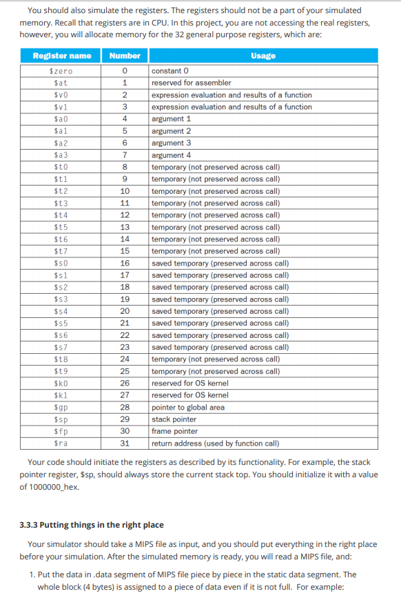
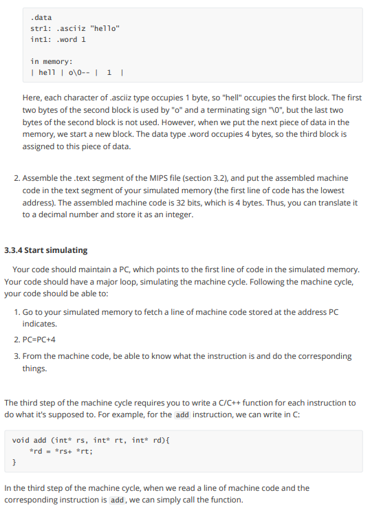
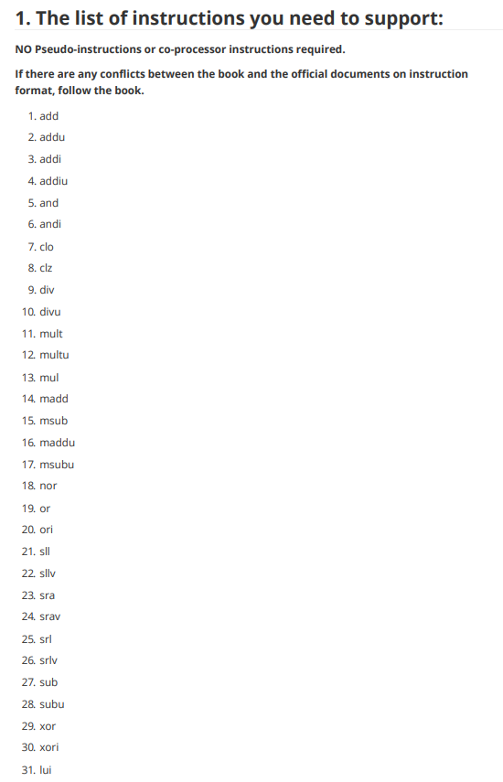
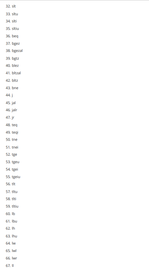
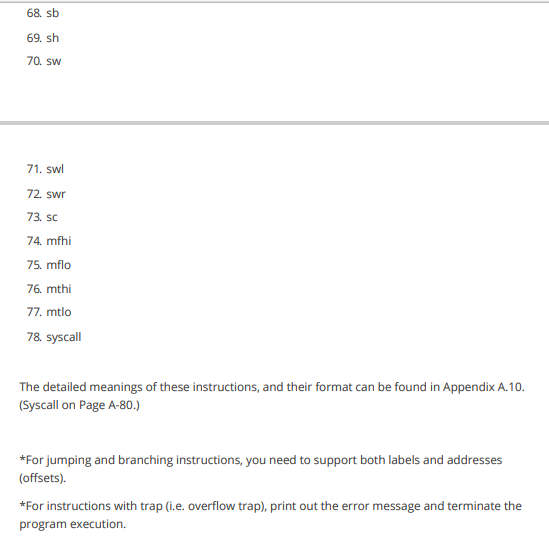
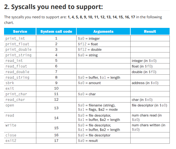
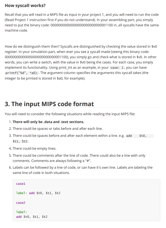
1. Overview The first project is going to be a MIPS simulator. In general, you will be building a program that simulates the execution of an assembly language file. The input of your program will be a MIPS file that contains MIPS assembly language code. Examples will be given in the latter part of this instruction 1.1 Readings: Please read Appendix A from the text book before you start writing your first project. Make sure you understand what each MIPS instruction is doing. All of the supplementary materials for this project can be found in Appendix A, such as the register numbers, instructions, and their machine code format. 2. MIPS MIPS is an assembly language, which is a low level programming language that each line of code corresponds to one machine instruction. 2.1 Instruction Machines cannot understand high level programming languages directly, such as C/C++/JAVA. High level programming languages are "translated" to machine instructions that machine can understand. Assembly languages, including MIPS we deal with, are the readable (although difficult) version of machine code. In assembly languages, one instruction tells the computer to do one thing exactly. For example, an instruction may look like this: add Sto, $t1, $t2 This instruction tells the computer to add up the things stored in register $t1 and register $t2 and store the result in $t3. Here, registers are small chunks of memory in CPU used for program execution. The MIPS assembly language has three types of instruction in general: l-type, R-type, and J-type, each corresponds to a pattern of the 32 bits of machine code. Details can be found in Appendix A of the text book. The above instruction has the machine code: 00000001001010100100000000100000 It does not make sense at a glance, however, it follows a certain pattern. The add instruction is a R-instruction, so it follows the pattern of: R-instruction: rs rt rd shamt funct | 6bits 5bits sbits | sbits | sbits 6bits | 1. op: operation code, all zeros for R-instructions. 2. rs: the first register operand 3. rt: the second register operand 4. rd: the destination register 5. shamt: shift amount. O when N/A 6. funct: function code, which is used to identify which R-instruction this is. The add instruction has the format: add $rd, Srs, $rt Therefore, for add $t0, $t1, $t2, we have: 0000000100101010 0100000000 100000 Here, we go through how this instruction and its machine code corresponds to each other. 1. The first 6 bits for R-instruction are for operation code, which are all zeros for R-type. 2. The following three 5-bit slots are the register numbers specified in the instruction. "rs" and "rt" represents the first and second register operand in the instruction, and "rd" represents the destination register. Here, the register number of Sto, $t1, and $t2 are 8, 9, 10, respectively. These translate to 01000, 01001, 01010 in binary, respectively. Putting them in the right place, we have the middle 15-bits. 3. "shamt" represents the shift amount, which are only in certain instructions (such as sli, srl), and O's are filled when N/A. In add instruction, these 5 bits are zeros. 4. The last 6 bits are for function code. The function code for add is 32, which is 100000 in binary. Machine codes of other R-instructions are constructed through the same process. As for l- instructions and J-instructions, I will not go through an example. The formats of these two types of instructions are: I-instruction: rs rt | 6bits 5bits sbits | immediate 16bits 1. op: the operation code that specifies which I-instruction this is. 2. rs: register that contains the base address 3. rt: the destination/source register (depends on the operation) 4. immediate: a numerical value or offset (depends on the operation) J-instruction: |6bits address 26bits 1. op: the operation code that specifies which 3-instruction this is. 2. address: the address to jump to, usually associate with a label. Since the address of an instruction in the memory is always divisible by 4 (think about why), the last two bits are always zero, so the last two bits are dropped. 2.2 MIPS programs Now you know what do MIPS instructions look like, but what does a MIPS program look like? Here is a general format a MIPS program follows: .data #static data go here stri: .asciiz "hello world! " .text #MIPS code goes here main: add Sto, $t1, $t2 In general, a MIPS program looks like this. All of the MIPS code goes under the text section, and all of the static data in the program are under .data section. As you can see, for each piece of static data, we have a name to it, just like what we do in high level programming languages. "str1" is the name to that piece of data, asciiz is the data type of it, and "hello world!n" is the value. There are many other types of data, you can find them in Appendix A. For the code part, as you can see, we also have a "name" called "main". This is the label representing the line of code. Usually this is used for indicating the start of a loop, a function, or a procedure. Recall that all of these codes are stored somewhere in the memory, which means that each line of code has a specific address. To better understand this, see section 2.3. 2.3 How computer runs the program? With the idea that all of the codes are stored in memory, and each has an address, we can now talk about how computers run these codes. Long story short, the computer runs the programs following the machine cycle. 2.3.1 Machine cycle A shorter version of a machine cycle looks like this: 1. The computer loads the line of instruction PC is "pointing at". 2. The computer increment PC by 4 (think about why). 3. The computer runs the instruction loaded. This goes on until the program terminates. PC in this context represents the "program counter". In other words, PC is the "pointer" the computer maintains that stores the address of the next instruction to be executed. 3. Project 1 details 3.1 Requirements 1. Your project 1 should be written in C/C++ only. 2. You will need to write your own makefile/cmake. 3.2 Assembler 3.2.1 Overview The first task you are doing is assembling the given MIPS code to their corresponding machine code. Here's a quick example of what you need to do: MIPS code: .text R: add $so, $s1, $s2 addu $so, $s1, $s2 sub $so, $s1, $s2 subu $so, $si, $s2 #r instructions Machine code: 00000010001100101000000000100000 00000010001100101000000000100001 00000010001100101000000000100010 00000010001100101000000000100011 Remember that you are not assembling the data section, nor the labels. The data section will be loaded to your memory in your simulation part. The labels in your.text section will be translated to its corresponding address when needed. For example, when you see j R, you will put the address of the line of instruction label R is indicating. 3.2.2 Details This part of your program is easy but needs your patience. You need to be able to: 1. Read file line by line. 2. Find the segments of the MIPS file. (data, text) 3. Tokenize the line read in. 4. Discard useless information, such as comments. Here are some ideas of how to implement this part: 1. You need to scan through the file for the first time. This time, discard all of the comments (following a "#"). Remember you only need to deal with text segment for assembling. Find all of the labels in the code, and store them with their corresponding address for later reference. 2. You need to scan through the file for the second time, line by line. This time, you need to identify which instruction the line is (R, 1,1). According to the instruction type, you can assemble the line. For lines with the label, you can refer to the stored information for the label's address. 3.3 Simulator 3.3.1 Overview This is the major part of your project 1. You need to have a full understanding of how computer executes programs, and how are things stored in memory. Your code will need to be capable of executing the MIPS code line by line. 3.3.2 Memory & register simulation The first thing you will need to do is memory simulation. Think about your simulator as a mini- computer, that has its own main memory, CPU, etc. To simulate main memory, you need to dynamically allocate a block of memory with C/C++, with a size of 6MB. Here is a figure of what does a real computer memory look like. 7fffffffnex Stack segment Dynamic data Static data Data segment 10000000 hex Text segment 400000 hex Reserved Your simulated memory should also have these components. Also, since most of you are using a 64-bit computer, you need to translate" the real address of your allocated memory to a 32-bit simulated address. Specifically: 1. Let's say you have the pointer named "real_mem" storing the real address of the block of memory allocated. The first thing you need to do is to map the value of "real_mem" to 400000_hex. Then the real address will have a 1-to-1 mapping relationship to the simulated address. For instance, if the address mentioned in the MIPS testing file is 500000_hex (such as lw, where we want to load the data storing on 500000_hex), then, you should access it at real address of: (real_mem + 500000_hex - 400000_hex). 2. The dynamically allocated 6MB memory block is pointing at the start of your text segment, and your text segment will be 1MB in size. The end of text segment will be at simulated address 400000_hex+1MB, or at address rea_mem+1MB. 3. The static data segment will start at simulated address 500000_hex, or at real address (real_mem+1 MB) 4. The dynamic data segment will start at wherever your static data section ends. 5. The stack segment will start at the highest address A00000_hex (real_mem+6MB), and it grows downwards (whenever you put things in there, the address decreases). 14 You should also simulate the registers. The registers should not be a part of your simulated memory. Recall that registers are in CPU. In this project, you are not accessing the real registers, however, you will allocate memory for the 32 general purpose registers, which are: Register name Number Usage $zero 0 constant o $at 1 reserved for assembler $v0 2 expression evaluation and results of a function $v1 3 expression evaluation and results of a function $a0 4 argument 1 $al 5 argument 2 $a 2 6 argument 3 $a 3 7 argument 4 $t0 8 temporary (not preserved across call) $t1 9 temporary (not preserved across call) $t 2 10 temporary (not preserved across call) $t3 11 temporary (not preserved across call) $t4 12 temporary (not preserved across call) $t5 13 temporary (not preserved across call) $t6 temporary (not preserved across call) $t7 15 temporary (not preserved across call) $50 16 saved temporary (preserved across call) $51 17 saved temporary (preserved across call) $s2 18 saved temporary (preserved across call) $s3 19 saved temporary (preserved across call) $54 20 saved temporary (preserved across call) $55 21 saved temporary (preserved across call) $S6 22 saved temporary (preserved across call) $57 23 saved temporary (preserved across call) $t8 24 temporary (not preserved across call) $t 9 25 temporary (not preserved across call) $KO 26 reserved for OS kernel $ki 27 reserved for OS kernel $gp 28 pointer to global area $SP 29 stack pointer $fp 30 frame pointer $ra 31 re address (used by function call) Your code should initiate the registers as described by its functionality. For example, the stack pointer register, $sp, should always store the current stack top. You should initialize it with a value of 1000000_hex. 3.3.3 Putting things in the right place Your simulator should take a MIPS file as input, and you should put everything in the right place before your simulation. After the simulated memory is ready, you will read a MIPS file, and: 1. Put the data in data segment of MIPS file piece by piece in the static data segment. The whole block (4 bytes) is assigned to a piece of data even if it is not full. For example: .data strl: asciiz "hello" inti: .word 1 in memory: | hell \0-- | 1 | Here, each character of asciiz type occupies 1 byte, so "hell" occupies the first block. The first two bytes of the second block is used by "o" and a terminating sign "0", but the last two bytes of the second block is not used. However, when we put the next piece of data in the memory, we start a new block. The data type.word occupies 4 bytes, so the third block is assigned to this piece of data. 2. Assemble the text segment of the MIPS file (Section 3.2), and put the assembled machine code in the text segment of your simulated memory (the first line of code has the lowest address). The assembled machine code is 32 bits, which is 4 bytes. Thus, you can translate it to a decimal number and store it as an integer. 3.3.4 Start simulating Your code should maintain a PC, which points to the first line of code in the simulated memory. Your code should have a major loop, simulating the machine cycle. Following the machine cycle, your code should be able to: 1. Go to your simulated memory to fetch a line of machine code stored at the address PC indicates. 2. PC=PC+4 3. From the machine code, be able to know what the instruction is and do the corresponding things. The third step of the machine cycle requires you to write a C/C++ function for each instruction to do what it's supposed to. For example, for the add instruction, we can write in C: void add (int* rs, int* rt, int* rd) { *rd*rs+ *rt; } In the third step of the machine cycle, when we read a line of machine code and the corresponding instruction is add, we can simply call the function. 1. The list of instructions you need to support: NO Pseudo-instructions or co-processor instructions required. If there are any conflicts between the book and the official documents on instruction format, follow the book. 1. add 2. addu 3. addi 4. addiu 5. and 6. andi 7. clo 8. clz 9. div 10. divu 11. mult 12. multu 13. mul 14. madd 15. msub 16. maddu 17. msubu 18. nor 19. or 20. ori 21. sll 22. sliv 23. sra 24 srav 25. srl 26. srlv 27. sub 28. subu 29. xor 30. xori 31. lui 32. slt 33. situ 34. slti 35. stiu 36. beq 37. bgez 38 bgezal 39. bgtz 40. blez 41. bltzal 42. bltz 43. bne 44.j 45. jal 46. jalr 47.jr 48. teq 49. teqi 50. tne 51. tnei 52 tge 53. tgeu 54. tgei 55. tgeiu 56. tit 57. titu 58. titi 59. titiu 60. lb 61. Ibu 62. In 63. Ihu 64. Iw 65. Iwl 66. lwr 67. II 68. sb 69. sh 70. sw 71. swl 72. swr 73. SC 74. mfhi 75. mflo 76. mthi 77. mtlo 78. syscall The detailed meanings of these instructions, and their format can be found in Appendix A.10. (Syscall on Page A-80.) *For jumping and branching instructions, you need to support both labels and addresses (offsets). *For instructions with trap (i.e. overflow trap), print out the error message and terminate the program execution. 4 6 2. Syscalls you need to support: The syscalls you need to support are: 1,4,5, 8, 9, 10, 11, 12, 13, 14, 15, 16, 17 in the following chart. Service System call code Arguments Result print_int 1 $a0 = integer print_float 2 $f12 = float print_double 3 $f12 = double print_string $a0 = string read_int 5 integer (in $v0) read_float float (in $f0) read_double 7 double (in $f0) read_string 8 $a0 = buffer, $al = length sbrk $a0 = amount address (in $v0) exit 10 print_char 11 $a0 = char read_char 12 char (in $v0) open $a0 = filename (string), file descriptor (in $a0) $al = flags, $a2 = mode read $a0 = file descriptor, num chars read (in $a1 = buffer, $a2 = length $a0) write $a0 = file descriptor, num chars written in 15 $a1 = buffer, $a2 = length $a0) close 16 $a0 = file descriptor exit2 17 $a0 = result 9 13 14 How syscall works? Recall that you will read in a MIPS file as input in your project 1, and you will need to run the code (Read Project 1 instruction first if you do not understand). In your assembling part, you simply need to put the binary code: 00000000000000000000000000001100 in, all syscalls have the same machine code. How do we distinguish them then? Syscalls are distinguished by checking the value stored in $vo register. In your simulation part, when ever you see a syscall made (seeing this binary code: 00000000000000000000000000001100), you simply go and check what is stored in $vo. In other words, you can write a switch, with the value in $vo being the cases. For each case, you simply implement its functionality. Using print_int as an example, in your case: 1, you can have printf("%d", *a0);. The argument column specifies the arguments this syscall takes (the integer to be printed is stored in $ao, for example). 3. The input MIPS code format You will need to consider the following situations while reading the input MIPS file: 1. There will only be .data and .text sections. 2. There could be spaces or tabs before and after each line. 3. There could be spaces before and after each element within a line. e.g, add Sto, stl, $t2. 4. There could be empty lines. 5. There could be comments after the line of code. There could also be a line with only comments. Comments are always following a "#". 6. Labels can be followed by a line of code, or can have it's own line. Labels are labeling the same line of code in both situations. casei label: add Sto, $t1, $t2 case2 Tabel: add $t0,$t1, St2 4. The data types you need to support The data types you need to support are: 1. ascii 2. asciiz 3. word 4. byte 5. half
Step by Step Solution
There are 3 Steps involved in it

Get step-by-step solutions from verified subject matter experts