Answered step by step
Verified Expert Solution
Question
1 Approved Answer
Given a mechanism with the link lengths L1x = 0.62 m, L1y = 0.19 m, L = 0.325 m, L3 = 0.16 m, and


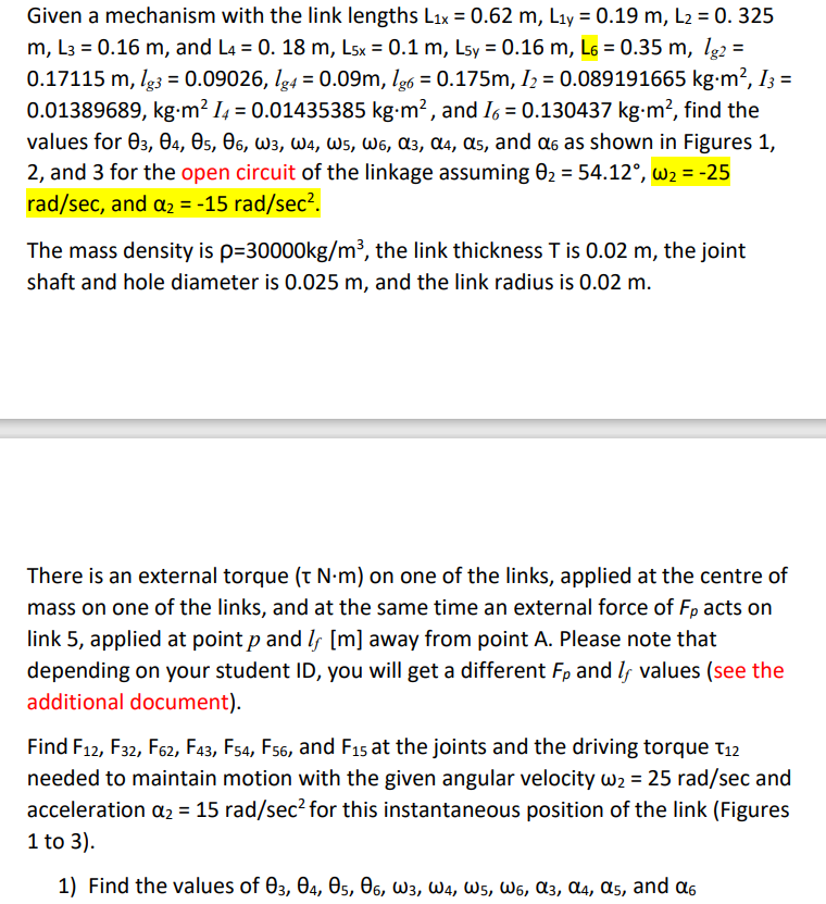
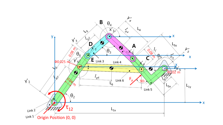
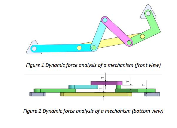
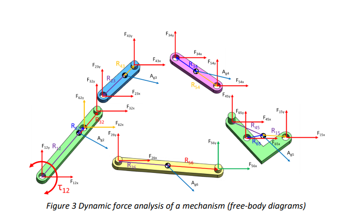
Given a mechanism with the link lengths L1x = 0.62 m, L1y = 0.19 m, L = 0.325 m, L3 = 0.16 m, and L4 = 0. 18 m, L5x = 0.1 m, L5y = 0.16 m, L6 = 0.35 m, lg2 = 0.17115 m, lg3 = 0.09026, 1g4 = 0.09m, lg6 = 0.175m, I2 = 0.089191665 kg.m, I3 = 0.01389689, kg.m 14 = 0.01435385 kgm, and 16 = 0.130437 kgm, find the values for 03, 04, 05, 06, W3, W4, W5, W6, 3, 4, s, and as shown in Figures 1, 2, and 3 for the open circuit of the linkage assuming 0 = 54.12, w = -25 rad/sec, and = -15 rad/sec. The mass density is p=30000kg/m, the link thickness T is 0.02 m, the joint shaft and hole diameter is 0.025 m, and the link radius is 0.02 m. There is an external torque (t Nm) on one of the links, applied at the centre of mass on one of the links, and at the same time an external force of Fp acts on link 5, applied at point p and I, [m] away from point A. Please note that depending on your student ID, you will get a different Fp and I values (see the additional document). Find F12, F32, F62, F43, F54, F56, and F15 at the joints and the driving torque T12 needed to maintain motion with the given angular velocity w = 25 rad/sec and acceleration a = 15 rad/sec for this instantaneous position of the link (Figures 1 to 3). 1) Find the values of 03, 04, 05, 06, W3, W4, W5, W6, 3, 4, s, and y' $0.025 V'3 5 L3 13 04 Y'A 184 LA X Lsy 0.08 m y' 6 D E Link 3 03 Link 4 A 0.04 m 02 Link 2 T12 Link 1 Origin Position (0, 0) 186 46 F Link 6 P L1x 0.08 m Link 5 ROOZ m L1y X Figure 1 Dynamic force analysis of a mechanism (front view) Figure 2 Dynamic force analysis of a mechanism (bottom view) Fizy R F6zy F43 Fax Agd Fax R43 F2BY Ap RS4 Fasy Fisy R3 Fxzy Fesy FASK F23x F15 RAS R15 F32x Fasx 32 Fozx R Fzov F12K Ag F26x Rs R26 Agi Fser T12 Figure 3 Dynamic force analysis of a mechanism (free-body diagrams)
Step by Step Solution
There are 3 Steps involved in it
Step: 1

Get Instant Access to Expert-Tailored Solutions
See step-by-step solutions with expert insights and AI powered tools for academic success
Step: 2

Step: 3

Ace Your Homework with AI
Get the answers you need in no time with our AI-driven, step-by-step assistance
Get Started


